BRAKE CONTROL / DYNAMIC CONTROL SYSTEMS BRAKE CONTROL POWER SUPPLY REMOVAL
CAUTION / NOTICE / HINT
- NOTICE:
- ·
After the ignition switch is turned off, the radio and display receiver assembly records various types of memory and settings. As a result, after turning the ignition switch off, make sure to wait at least 3 minutes before disconnecting the cable from the negative (-) auxiliary battery terminal.
·When the cable is disconnected from the negative (-) auxiliary battery terminal and the security lock setting has been enabled, multi-display operations will be disabled upon next startup unless the password is entered. Be sure to check the security lock setting before disconnecting the cable from the negative (-) auxiliary battery terminal. (for Audio and Visual System (for Single Knob Type))
- HINT:
-
When the cable is disconnected / reconnected to the auxiliary battery terminal, systems temporarily stop operating. However, each system has a function that completes learning the first time the system is used.
Learning completes when vehicle is driven Effect/Inoperative Function When Necessary Procedures are not Performed Necessary Procedures Link Front Camera System Drive the vehicle straight ahead at 35 km/h (22 mph) or more for 5 seconds or more. (  202304,999999,_95,_139716,_0584193,RM1000000029F4C,)
PROCEDURE

 1. PRECAUTION
- NOTICE:
-
After turning the ignition switch off, waiting time may be required before disconnecting the cable from the negative (-) auxiliary battery terminal.
2.DISCONNECT CABLE FROM NEGATIVE AUXILIARY BATTERY TERMINAL
for 8ZR-FXE: Click hereGeneral>MAINTENANCE>8ZR-FXE AUXILIARY BATTERY>REMOVAL202304,999999,_V1,_080956,_0392376,RM100000002ACL7,
for M20F-FXS, M20G-FXS: Click hereGeneral>MAINTENANCE>M20F-FXS, M20G-FXS AUXILIARY BATTERY>REMOVAL202307,999999,_V1,_080956,_0611807,RM100000002CK9K,
3.REMOVE FRONT SEAT ASSEMBLY RH
89680
4.REMOVE BRAKE CONTROL POWER SUPPLY ASSEMBLY
- CAUTION:
-
After removing the brake control power supply assembly from the vehicle, there may be an electrical charge left in the internal capacitor. If planning to inspect the inside of the brake control power supply assembly, leave it as is for more than 24 hours (to discharge it) after removing it from the vehicle. Then, perform the inspection.
- NOTICE:
- ·
Do not hold the brake control power supply assembly by the connector.
·Do not drop the brake control power supply assembly when carrying it.
Turn back the floor carpet.
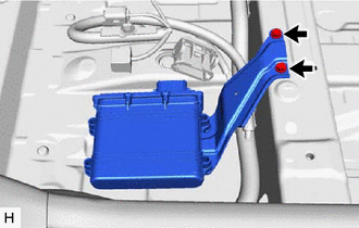
Remove the 2 bolts and remove the brake control power supply assembly.
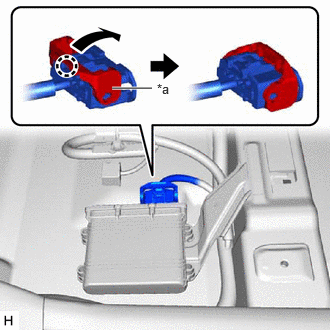
| *a | Lock Lever |
Disconnect the brake control power supply assembly connector.
Disengage the claw and raise the lock lever to disconnect the brake control power supply assembly connector as shown in the illustration.
- NOTICE:
-
After disconnecting the brake control power supply assembly connector, make sure that dirt, water or other foreign matter does not contact the connecting parts of the brake control power supply assembly connector.
89686A
5.REMOVE NO.1 BRAKE CONTROL POWER SUPPLY BRACKET
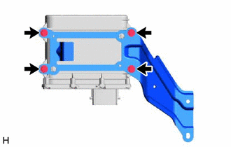
Remove the 4 bolts and No. 1 brake control power supply bracket.
- NOTICE:
- ·
Do not hold the brake control power supply assembly by the connector.
·Do not drop the brake control power supply assembly when carrying it.