BRAKE SYSTEM (OTHER) BRAKE PEDAL(for HV Model) REMOVAL
CAUTION / NOTICE / HINT
The necessary procedures (adjustment, calibration, initialization, or registration) that must be performed after parts are removed, installed, or replaced during brake pedal support assembly removal/installation are shown below.
| Replaced Part or Performed Procedure | Necessary Procedure | Effect/Inoperative Function when Necessary Procedure not Performed | Link |
|---|---|---|---|
| Removal/installation/replacement of brake pedal support assembly | 1.
Perform "Reset Memory" 2.
Perform "Calibration" |
·
DTCs are stored ·
ABS warning light illuminates ·
Brake system warning light (yellow indicator) illuminates ·
Slip indicator light illuminates ·
Electronically controlled brake system disabled or malfunctions |
( 202304,999999,_54,_080770,_0392591,RM100000002B671,) 202304,999999,_54,_080770,_0392591,RM100000002B671,)
|
- HINT:
-
When the cable is disconnected / reconnected to the auxiliary battery terminal, systems temporarily stop operating. However, each system has a function that completes learning the first time the system is used.
Learning completes when vehicle is driven Effect/Inoperative Function when Necessary Procedure not Performed Necessary Procedures Link Front Camera System Drive the vehicle straight ahead at 15 km/h (9 mph) or more for 1 second or more. ( 202304,999999,_95,_139716,_0584193,RM1000000029F4C,)
- NOTICE:
-
After turning the ignition switch off, waiting time may be required before disconnecting the cable from the negative (-) auxiliary battery terminal. Therefore, make sure to read the disconnecting the cable from the negative (-) auxiliary battery terminal notices before proceeding with work.
PROCEDURE

 1.DISCONNECT CABLE FROM NEGATIVE AUXILIARY BATTERY TERMINAL
for M20F-FXS, M20G-FXS: Click hereGeneral>MAINTENANCE>M20F-FXS, M20G-FXS AUXILIARY BATTERY>REMOVAL202307,999999,_V1,_080956,_0611807,RM100000002CK9K,
for 8ZR-FXE: Click hereGeneral>MAINTENANCE>8ZR-FXE AUXILIARY BATTERY>REMOVAL202304,999999,_V1,_080956,_0392376,RM100000002ACL7,
67914
2.REMOVE FRONT DOOR SCUFF PLATE LH
62112A
3.REMOVE COWL SIDE TRIM SUB-ASSEMBLY LH
55606
4.REMOVE NO. 1 INSTRUMENT PANEL UNDER COVER SUB-ASSEMBLY
55317E
5.REMOVE NO. 1 INSTRUMENT SIDE PANEL
53601
6.DISCONNECT HOOD LOCK CONTROL LEVER SUB-ASSEMBLY
55432B
7.REMOVE LOWER INSTRUMENT PANEL FINISH PANEL
58816D
8.REMOVE FRONT NO. 1 CONSOLE BOX INSERT
55434F
9.REMOVE LOWER CENTER INSTRUMENT PANEL FINISH PANEL
58831A
10.REMOVE FRONT CONSOLE UPPER PANEL GARNISH
87211
11.REMOVE NO. 1 AIR DUCT
89510D
12.REMOVE BRAKE PEDAL STROKE SENSOR ASSEMBLY
84340
13.REMOVE STOP LIGHT SWITCH ASSEMBLY
47101A
14.REMOVE BRAKE PEDAL RETURN SPRING
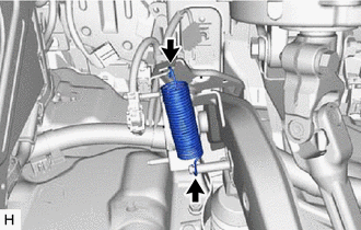
Remove the brake pedal return spring from the brake pedal support assembly and push rod pin.
47264A
15.REMOVE PUSH ROD PIN
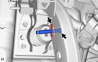
Remove the clip and push rod pin to separate the brake pedal support assembly from the brake master cylinder push rod clevis.
47110
16.REMOVE BRAKE PEDAL SUPPORT ASSEMBLY
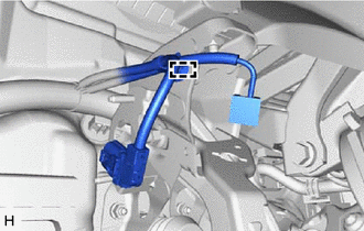
Disengage the clamp to separate the wire harness from the brake pedal support assembly.
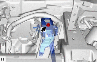
Remove the bolt and separate the brake pedal support assembly from the instrument panel reinforcement assembly.
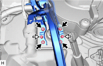

|
Nut |

|
Clip |
Remove the 2 clips.
Remove the 4 nuts and brake pedal support assembly.
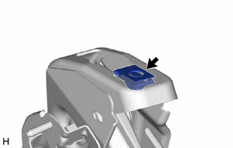
Remove the nut from the brake pedal support assembly.
84345
17.REMOVE STOP LIGHT SWITCH MOUNTING ADJUSTER
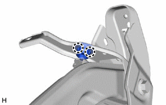
Disengage the 2 claws and remove the stop light switch mounting adjuster.
47121
18.REMOVE BRAKE PEDAL PAD
Remove the brake pedal pad from the brake pedal support assembly.