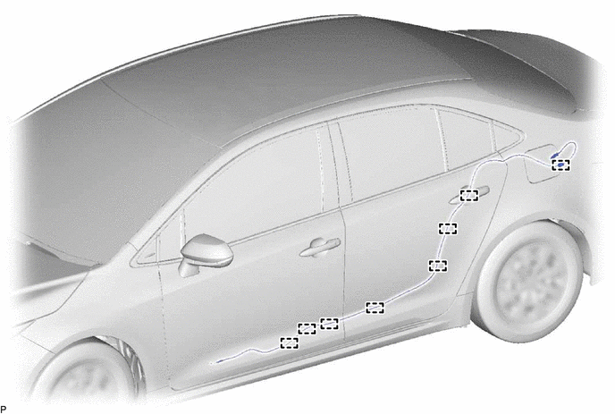
DOOR / HATCH FUEL LID LOCK CONTROL CABLE ASSEMBLY REMOVAL
CAUTION / NOTICE / HINT
The necessary procedures (adjustment, calibration, initialization or registration) that must be performed after parts are removed and installed, or replaced during fuel lid lock control cable sub-assembly removal/installation are shown below.
- CAUTION:
-
-
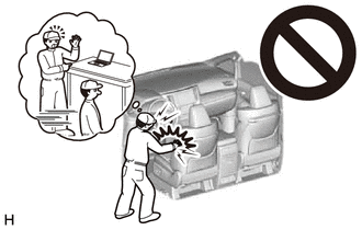
Be sure to read Precaution thoroughly before servicing.
-
except NR Series Engine:
-
for NR Series Engine:
- NOTICE:
-
After the ignition switch is turned off, there may be a waiting time before disconnecting the negative (-) auxiliary battery terminal.
- HINT:
-
When the cable is disconnected / reconnected to the auxiliary battery terminal, systems temporarily stop operating. However, each system has a function that completes learning the first time the system is used.
- ·
for HV Model:
Items for which learning is completed by driving the vehicle Effect/Inoperative Function When Necessary Procedures are not Performed Necessary Procedures Link Front Camera System Drive the vehicle straight ahead at 15 km/h (9 mph) or more for 1 second or more. (  202304,999999,_95,_139716,_0584193,RM1000000029F4C,)
·for Gasoline Model:
Items for which learning is completed by driving the vehicle Effect/Inoperative Function When Necessary Procedures are not Performed Necessary Procedures Link Stop and Start System Idle the engine for approximately 5 to 60 minutes or drive the vehicle until stop and start control is permitted ( 201906,999999,_51,_080774,_0393362,RM100000001HXHC,)
Pre-collision System Perform steering sensor zero point calibration ( 202304,999999,_95,_139716,_0601175,RM100000002BFOE,)
Lane Tracing Assist System Front Camera System Drive the vehicle straight ahead at 15 km/h (9 mph) or more for 1 second or more. ( 202304,999999,_95,_139716,_0584193,RM1000000029F4C,)
PROCEDURE

 1.REMOVE FRONT SEAT ASSEMBLY LH
2.REMOVE REAR SEAT ASSEMBLY
for Fixed Seat Type:
for Fold Down Seat Type:
3.REMOVE ROOM PARTITION PANEL LH (for Fixed Seat Type)
4.REMOVE ROOM PARTITION PANEL RH (for Fixed Seat Type)
5.REMOVE LUGGAGE COVER (for Fixed Seat Type)
67918A
6.REMOVE REAR DOOR SCUFF PLATE LH (for Gasoline Model)
67917A
7.REMOVE REAR DOOR SCUFF PLATE RH (for Gasoline Model)
- HINT:
-
Use the same procedure as for the LH side.
67918A
8.REMOVE REAR DOOR SCUFF PLATE LH (for HV Model)
67917A
9.REMOVE REAR DOOR SCUFF PLATE RH (for HV Model)
- HINT:
-
Use the same procedure as for the LH side.
76974F
10.REMOVE REAR UNDER SIDE COVER LH (for HV Model)
76973F
11.REMOVE REAR UNDER SIDE COVER RH (for HV Model)
- HINT:
-
Use the same procedure as for the LH side.
62332A
12.REMOVE REAR DOOR OPENING TRIM WEATHERSTRIP LH
62331A
13.DISCONNECT REAR DOOR OPENING TRIM WEATHERSTRIP RH
- HINT:
-
Use the same procedure as for the LH side.
62552F
14.REMOVE REAR SEAT SIDE GARNISH LH
62551F
15.REMOVE REAR SEAT SIDE GARNISH RH
- HINT:
-
Use the same procedure as for the LH side.
67914
16.REMOVE FRONT DOOR SCUFF PLATE LH
62112A
17.REMOVE COWL SIDE TRIM SUB-ASSEMBLY LH
62312B
18.DISCONNECT FRONT DOOR OPENING TRIM WEATHERSTRIP LH
73233
19.REMOVE LAP BELT OUTER ANCHOR COVER
73220
20.DISCONNECT FRONT SEAT OUTER BELT ASSEMBLY LH
62414A
21.REMOVE CENTER PILLAR LOWER GARNISH LH
62472A
22.REMOVE ROOF SIDE INNER GARNISH LH
62471A
23.REMOVE ROOF SIDE INNER GARNISH RH
- HINT:
-
Use the same procedure as for the LH side.
81006
24.REMOVE CENTER STOP LIGHT SET
64322A
25.REMOVE PACKAGE TRAY TRIM BRACKET LH
64321F
26.REMOVE PACKAGE TRAY TRIM BRACKET RH
- HINT:
-
Use the same procedure as for the LH side.
73373F
27.REMOVE REAR SEAT SHOULDER BELT HOLE COVER
64330
28.REMOVE PACKAGE TRAY TRIM PANEL ASSEMBLY
64771
29.REMOVE SPARE WHEEL COVER
58387
30.REMOVE REAR FLOOR FINISH PLATE
64720A
31.REMOVE LUGGAGE COMPARTMENT TRIM COVER ASSEMBLY LH
77306
32.REMOVE FUEL LID LOCK OPEN LEVER SUB-ASSEMBLY
77377
33.REMOVE FUEL FILLER OPENING LID LOCK RETAINER
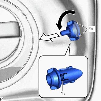
| *a | Cutout |
| *b | Guide (A) |
Rotate the fuel filler opening lid lock retainer as shown in the illustration to align the cutouts and the guides (A), and then pull the fuel filler opening lid lock retainer.
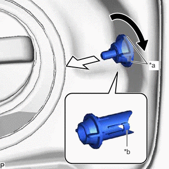
| *a | Cutout |
| *b | Guide (B) |
Rotate the fuel filler opening lid lock retainer as shown in the illustration to align the cutouts and the guides (B), and then pull the fuel filler opening lid lock retainer.
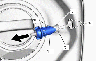
| *a | Cutout |
| *b | Guide (B) |
| *c | Guide (C) |
Pull out the fuel filler opening lid lock retainer with both the guides (B) and guides (C) aligned with the cutouts as shown in the illustration.
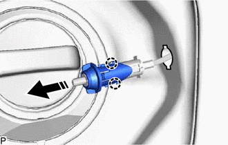

|
Remove in this Direction |
Disengage the 2 claws to remove the fuel filler opening lid lock retainer as shown in the illustration.
77035
34.REMOVE FUEL LID LOCK CONTROL CABLE SUB-ASSEMBLY
Turn back the floor carpet so that the fuel lid lock control cable sub-assembly can be removed.
Disengage each clamp and remove the fuel lid lock control cable sub-assembly.