PA10/PB10 HYBRID TRANSMISSION / TRANSAXLE INPUT SHAFT OIL SEAL REPLACEMENT
CAUTION / NOTICE / HINT
The necessary procedures (adjustment, calibration, initialization or registration) that must be performed after parts are removed and installed, or replaced during input shaft type T oil seal removal/installation are shown below.
| Replaced Part or Performed Procedure | Necessary Procedure | Effect/Inoperative Function when Necessary Procedure not Performed | Link |
|---|---|---|---|
|
*: The vehicle height changes because of tire replacement. |
|||
| Replacement of ECM | Vehicle Identification Number (VIN) or frame number registration | DTC stored | for 8ZR-FXE:( 202304,999999,_51,_080778,_0393982,RM100000002BDLH,) 202304,999999,_51,_080778,_0393982,RM100000002BDLH,)
for M20F-FXS, M20G-FXS:( 202307,999999,_51,_146896,_0611112,RM100000002CI3X,)
|
| ECU configuration | - | (202304,999999,_V1,_143216,_0598316,RM100000002B3MK,)
|
|
| Update ECU security key | Vehicle Control History (RoB) are stored | (202304,999999,_V1,_143216,_0598316,RM100000002B3ML,)
|
|
| Perform Total Short Trip Estimate Registration | - | for 8ZR-FXE:(202304,999999,_51,_080778,_0393982,RM100000002BDLH,)
for M20F-FXS, M20G-FXS:( 202307,999999,_51,_146896,_0611112,RM100000002CI3X,)
|
|
| Replacement of inverter with converter assembly | ECU configuration | - | (202304,999999,_V1,_143216,_0598316,RM100000002B3MK,)
|
| Resolver learning | ·
DTCs are stored ·
Slight vibration at a vehicle speed of 5 km/h (3 mph) or less ·
Shock or vibration during acceleration |
for 8ZR-FXE:(202304,999999,_51,_080773,_0600292,RM100000002BBW3,)
for M20F-FXS, M20G-FXS:( 202307,999999,_51,_080773,_0615952,RM100000002CVBZ,)
|
|
for 8ZR-FXE
·
Replacement of throttle body assembly ·
Replacement of engine assembly ·
Gas leak from exhaust system is repaired |
Inspection after repair | ·
Poor idle, etc. ·
Engine start function, etc. |
(202304,999999,_51,_080778,_0393982,RM100000002BDLI,)
|
for M20F-FXS, M20G-FXS
·
Replacement of engine assembly ·
Gas leak from exhaust system is repaired |
Inspection after repair | ·
Poor idle, etc. ·
Engine start function, etc. |
(202307,999999,_51,_146896,_0611112,RM100000002CI3Y,)
|
| Replacement of hybrid vehicle transaxle assembly | ·
Resolver learning ·
Initialize resolver |
·
DTCs are stored ·
Slight vibration at a vehicle speed of 5 km/h (3 mph) or less |
for 8ZR-FXE:(202304,999999,_51,_080773,_0600292,RM100000002BBW3,)
for M20F-FXS, M20G-FXS:( 202307,999999,_51,_080773,_0615952,RM100000002CVBZ,)
|
| Front wheel alignment adjustment | 1.
Perform "Reset Memory" 2.
Perform "Calibration" |
·
DTCs are stored ·
ABS warning light illuminates ·
Brake system warning light (yellow indicator) illuminates ·
Slip indicator light illuminates ·
Electronically controlled brake system disabled or malfunctions |
(202304,999999,_54,_080770,_0392591,RM100000002B671,)
|
·
Tires ·
Suspension parts |
Rear television camera assembly optical axis (Back camera position setting)* | Parking Assist Monitor System | (202304,999999,_56,_080754,_0596561,RM100000002AX0C,)
|
| Parking assist ECU initialization | Panoramic View Monitor System | (202307,999999,_56,_080754,_0612151,RM100000002CL9H,)
|
|
- CAUTION:
- ·
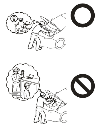
Orange wire harnesses and connectors indicate high-voltage circuits. To prevent electric shock, always follow the procedure described in the repair manual.
-
·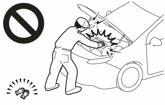
To prevent electric shock, wear insulated gloves when working on wire harnesses and components of the high voltage system.
·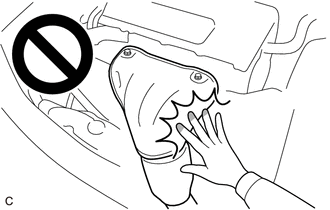
To prevent burns, do not touch the engine, exhaust manifold or other high temperature components while the engine is hot.
·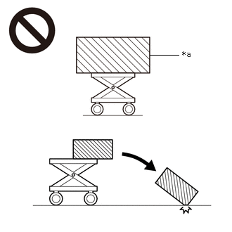 2.219,0.813 2.646,0.813 false 2.698,0.729 3.01,0.927 0.313,0.198 10 false *a
*a An Object Exceeding Weight Limit of Engine Lifter
The engine assembly with transaxle is very heavy. Be sure to follow the procedure described in the repair manual, or the engine lifter may suddenly drop or the engine assembly with transaxle may fall off the engine lifter.
- HINT:
-
When the cable is disconnected / reconnected to the auxiliary battery terminal, systems temporarily stop operating. However, each system has a function that completes learning the first time the system is used.
Learning completes when vehicle is driven Effect/Inoperative Function when Necessary Procedure not Performed Necessary Procedure Link Front Camera System Drive the vehicle straight ahead at 15 km/h (9 mph) or more for 1 second or more. ( 202304,999999,_95,_139716,_0584193,RM1000000029F4C,)
PROCEDURE

 30900
1.REMOVE HYBRID VEHICLE TRANSAXLE ASSEMBLY
30900
1.REMOVE HYBRID VEHICLE TRANSAXLE ASSEMBLY
35710A
2.REMOVE INPUT SHAFT TYPE T OIL SEAL
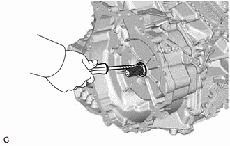
| *a | Protective Tape |
Using a screwdriver with its tip wrapped with protective tape, remove the input shaft type T oil seal from the hybrid vehicle transaxle assembly.
- NOTICE:
-
Be careful not to damage the input shaft assembly or hybrid vehicle transaxle assembly.
35710A
3.INSTALL INPUT SHAFT TYPE T OIL SEAL
Coat the lip of a new input shaft type T oil seal with a small amount of MP grease.
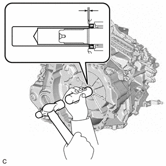
| *a | Depth |
Using SST and a hammer, install the input shaft type T oil seal to the hybrid vehicle transaxle assembly.
- SST
- 09608-04031
- Standard Depth:
- for PA10:
1.0 to 1.8 mm (0.0394 to 0.0709 in.)
- for PB10:
3.3 to 4.5 mm (0.130 to 0.177 in.)
- NOTICE:
- ·
Do not allow foreign matter to attach to the lip of the input shaft type T oil seal.
·Do not install the input shaft type T oil seal at an angle.
30900
4.INSTALL HYBRID VEHICLE TRANSAXLE ASSEMBLY