HEATING / AIR CONDITIONING COMPRESSOR(for 8ZR-FXE) REMOVAL
CAUTION / NOTICE / HINT
The necessary procedures (adjustment, calibration, initialization or registration) that must be performed after parts are removed and installed, or replaced during compressor with motor assembly removal/installation are shown below.
- CAUTION:
- ·
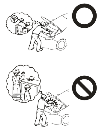
Orange wire harnesses and connectors indicate high-voltage circuits. To prevent electric shock, always follow the procedure described in the repair manual.
·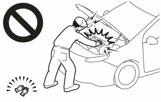
To prevent electric shock, wear insulated gloves when working on wire harnesses and components of the high voltage system.
CAUTION / NOTICE / HINT
- NOTICE:
-
After the ignition switch is turned off, there may be a waiting time before disconnecting the negative (-) auxiliary battery terminal.
- HINT:
-
When the cable is disconnected / reconnected to the auxiliary battery terminal, systems temporarily stop operating. However, each system has a function that completes learning the first time the system is used.
Learning completes when vehicle is driven Effect/Inoperative Function When Necessary Procedures are not Performed Necessary Procedures Link Front Camera System Drive the vehicle straight ahead at 15 km/h (9 mph) or more for 1 second or more. (  202304,999999,_95,_139716,_0584193,RM1000000029F4C,)
PROCEDURE

 1.RECOVER REFRIGERANT FROM REFRIGERATION SYSTEM
G3834
2.REMOVE SERVICE PLUG GRIP
3.CHECK TERMINAL VOLTAGE
Remove the connector cover assembly.
Check the terminal voltage.
53289A
4.REMOVE RADIATOR SUPPORT OPENING COVER (for TFTM Made)
53289A
5.REMOVE RADIATOR SUPPORT OPENING COVER (for GTMC Made)
17752
6.REMOVE INLET NO. 2 AIR CLEANER
17705
7.REMOVE AIR CLEANER CAP SUB-ASSEMBLY
8.REMOVE AIR CLEANER HOSE ASSEMBLY
17801
9.REMOVE AIR CLEANER FILTER ELEMENT SUB-ASSEMBLY
17701
10.REMOVE AIR CLEANER CASE SUB-ASSEMBLY
17771A
11.REMOVE AIR CLEANER BRACKET
17751
12.REMOVE INLET NO. 1 AIR CLEANER
88703
13.DISCONNECT DISCHARGE HOSE SUB-ASSEMBLY
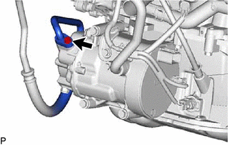
Remove the bolt and disconnect the discharge hose sub-assembly from the compressor with motor assembly.
Remove the O-ring from the discharge hose sub-assembly.
- NOTICE:
-
Seal the openings of the disconnected parts using vinyl tape to prevent moisture and foreign matter from entering them.
88704
14.DISCONNECT SUCTION HOSE SUB-ASSEMBLY
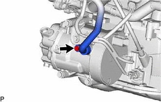
Remove the bolt and disconnect the suction hose sub-assembly from the compressor with motor assembly.
Remove the O-ring from the suction hose sub-assembly.
- NOTICE:
-
Seal the openings of the disconnected parts using vinyl tape to prevent moisture and foreign matter from entering them.
88370
15.REMOVE COMPRESSOR WITH MOTOR ASSEMBLY
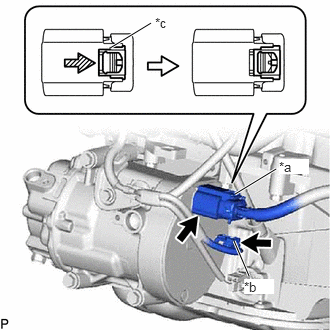
| *a | Connector (A) |
| *b | Connector (B) |
| *c | Green-colored Lock |

|
Slide |
Using a screwdriver, slide the green-colored lock of the connector (A) as shown in the illustration to release it and disconnect the connector.
- CAUTION:
-
Make sure to wear insulated gloves.
- NOTICE:
-
Insulate the disconnected terminals and connector with insulating tape.
Disconnect the connector (B).
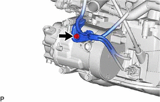
Remove the bolt and disconnect the bracket.
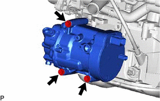
Remove the 3 bolts and compressor with motor assembly.