RM3660EC _51 Engine / Hybrid System _080778 8ZR-FXE ENGINE CONTROL _0393982 SFI SYSTEM J

8ZR-FXE ENGINE CONTROL  SFI SYSTEM  Ignition Circuit  


DESCRIPTION

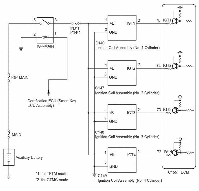
A direct ignition system is used on this vehicle. The direct ignition system is a 1 cylinder ignition system which ignites one cylinder with one ignition coil. In the 1 cylinder ignition system, one spark plug is connected to the end of the secondary winding. High voltage is generated in the secondary winding and is applied directly to the spark plug. The spark of the spark plug passes from the center electrode to the ground electrode.

The ECM determines the ignition timing and transmits the ignition signals for each cylinder. Using the ignition signal, the ECM turns on and off the power transistor inside the igniter, which switches on and off a current to the primary coil. When the current to the primary coil is cut off, high voltage is generated in the secondary coil and this voltage is applied to the spark plugs to create sparks inside the cylinders.

WIRING DIAGRAM
A531782E08
6.052,6.094 6.615,6.385 0.563,0.292 10 false C155 6.51,6.094 6.969,6.292 0.458,0.198 10 false ECM 5.875,0.635 6.49,0.833 0.615,0.198 10 false IGT1 5.625,0.646 5.938,0.844 0.313,0.198 10 false 75 5.635,2.271 5.948,2.469 0.313,0.198 10 false 74 5.875,2.26 6.49,2.458 0.615,0.198 10 false IGT2 5.646,3.854 5.958,4.052 0.313,0.198 10 false 73 5.875,3.844 6.49,4.042 0.615,0.198 10 false IGT3 5.656,5.365 5.969,5.563 0.313,0.198 10 false 72 5.896,5.344 6.51,5.542 0.615,0.198 10 false IGT4 4.969,0.646 5.125,0.844 0.156,0.198 10 false 2 4.979,2.24 5.135,2.438 0.156,0.198 10 false 2 4.958,3.854 5.115,4.052 0.156,0.198 10 false 2 4.948,5.365 5.104,5.563 0.156,0.198 10 false 2 4.563,0.75 5.177,0.948 0.615,0.198 10 false IGT1 4.573,2.365 5.188,2.563 0.615,0.198 10 false IGT2 4.573,3.958 5.188,4.156 0.615,0.198 10 false IGT3 4.583,5.469 5.198,5.667 0.615,0.198 10 false IGT4 3.948,0.75 4.26,0.948 0.313,0.198 10 false +B 3.781,0.625 3.938,0.823 0.156,0.198 10 false 1 3.781,2.25 3.938,2.448 0.156,0.198 10 false 1 3.74,3.823 3.896,4.021 0.156,0.198 10 false 1 3.76,5.385 3.917,5.583 0.156,0.198 10 false 1 3.948,2.365 4.26,2.563 0.313,0.198 10 false +B 3.927,3.958 4.24,4.156 0.313,0.198 10 false +B 3.948,5.458 4.26,5.656 0.313,0.198 10 false +B 3.781,0.979 3.938,1.177 0.156,0.198 10 false 3 3.76,2.573 3.938,2.833 0.177,0.26 10 false 3 3.76,4.167 3.917,4.365 0.156,0.198 10 false 3 3.76,5.74 3.917,5.938 0.156,0.198 10 false 3 3.927,1.073 4.385,1.271 0.458,0.198 10 false GND 3.927,2.688 4.385,2.885 0.458,0.198 10 false GND 3.927,4.271 4.385,4.469 0.458,0.198 10 false GND 3.938,5.885 4.396,6.083 0.458,0.198 10 false GND 3.438,1.458 3.802,1.656 0.365,0.198 10 false C146 3.438,1.625 5.938,2.021 2.5,0.396 10 false Ignition Coil Assembly (No. 1 Cylinder) 3.427,3.073 3.802,3.271 0.375,0.198 10 false C147 3.427,3.25 5.833,3.542 2.406,0.292 10 false Ignition Coil Assembly (No. 2 Cylinder) 3.427,4.656 3.854,4.865 0.427,0.208 10 false C148 3.427,4.823 5.885,5.271 2.458,0.448 10 false Ignition Coil Assembly (No. 3 Cylinder) 3.521,6.219 3.979,6.417 0.458,0.198 10 false C149 3.521,6.385 5.979,6.74 2.458,0.354 10 false Ignition Coil Assembly (No. 4 Cylinder) 2.531,0.927 2.948,1.302 0.417,0.375 10 false INJ*1, IGN*2 1.969,0.625 2.125,0.823 0.156,0.198 10 false 3 1.958,1.125 2.115,1.323 0.156,0.198 10 false 1 1.208,1.146 1.365,1.344 0.156,0.198 10 false 2 1.208,0.625 1.365,0.823 0.156,0.198 10 false 5 0.406,2.698 1.635,2.896 1.229,0.198 10 false IGP-MAIN 0.427,4.74 1.042,4.938 0.615,0.198 10 false MAIN 0.99,3.531 2.792,4.073 1.802,0.542 10 false Certification ECU (Smart Key ECU Assembly) 0.563,5.563 1.729,5.875 1.167,0.313 10 false Auxiliary Battery 1.323,1.573 2.552,1.771 1.229,0.198 10 false IGP-MAIN 1.292,6.146 3.896,6.344 2.604,0.198 10 false *1: for TFTM made 1.281,6.365 3.885,6.563 2.604,0.198 10 false *2: for GTMC made

CAUTION / NOTICE / HINT

NOTICE:

Inspect the fuses for circuits related to this system before performing the following procedure.


HINT:

Perform a spark test before proceeding. If there is no spark for any cylinder, inspect this circuit.

Click hereEngine / Hybrid System>8ZR-FXE (ENGINE CONTROL)>IGNITION SYSTEM>ON-VEHICLE INSPECTION


PROCEDURE

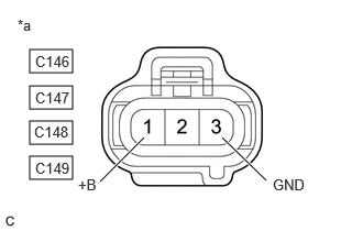
1.CHECK TERMINAL VOLTAGE (POWER SOURCE OF IGNITION COIL ASSEMBLY)
A402447C59
0.281,0.469 0.688,0.688 0.406,0.219 0.281,0.813 0.688,1.031 0.406,0.219 0.281,1.146 0.688,1.365 0.406,0.219 0.281,1.479 0.688,1.698 0.406,0.219 0.948,1.719 1.365,1.302 true 2.521,1.708 2.104,1.302 true 0.167,0.156 0.479,0.354 0.313,0.198 10 false *a 0.74,1.667 1.052,1.865 0.313,0.198 10 false +B 2.583,1.667 2.896,1.865 0.313,0.198 10 false GND 0.333,0.5 0.719,0.698 0.385,0.198 10 false C146 0.333,0.844 0.698,1.042 0.365,0.198 10 false C147 0.323,1.167 0.75,1.375 0.427,0.208 10 false C148 0.333,1.51 0.708,1.719 0.375,0.208 10 false C149
*a Front view of wire harness connector
(to Ignition Coil Assembly)


a.

Disconnect the ignition coil assembly connectors.


b.

Turn the power switch on (IG).


c.

Measure the voltage according to the value(s) in the table below.

Standard Voltage:
Tester Connection Condition Specified Condition
C146-1 (+B) - C146-3 (GND) Power switch on (IG) 11 to 14 V
C147-1 (+B) - C147-3 (GND) Power switch on (IG) 11 to 14 V
C148-1 (+B) - C148-3 (GND) Power switch on (IG) 11 to 14 V
C149-1 (+B) - C149-3 (GND) Power switch on (IG) 11 to 14 V


Result:
Proceed to
OK
NG


OK

2.CHECK HARNESS AND CONNECTOR (IGNITION COIL ASSEMBLY - ECM)

NG

3.CHECK HARNESS AND CONNECTOR (IGNITION COIL ASSEMBLY - BODY GROUND)
2.CHECK HARNESS AND CONNECTOR (IGNITION COIL ASSEMBLY - ECM)
a.

Disconnect the ignition coil assembly connectors.


b.

Disconnect the ECM connector.


c.

Measure the resistance according to the value(s) in the table below.

Standard Resistance:
Tester Connection Condition Specified Condition
C146-2 (IGT1) - C155-75 (IGT1) Always Below 1 Ω
C147-2 (IGT2) - C155-74 (IGT2) Always Below 1 Ω
C148-2 (IGT3) or C155-73 (IGT3) Always Below 1 Ω
C149-2 (IGT4) or C155-72 (IGT4) Always Below 1 Ω
C146-2 (IGT1) - C155-75 (IGT1) - Body ground and other terminals Always 10 kΩ or higher
C147-2 (IGT2) - C155-74 (IGT2) - Body ground and other terminals Always 10 kΩ or higher
C148-2 (IGT3) or C155-73 (IGT3) - Body ground and other terminals Always 10 kΩ or higher
C149-2 (IGT4) or C155-72 (IGT4) - Body ground and other terminals Always 10 kΩ or higher


Result:
Proceed to
OK
NG


OK

NG

REPAIR OR REPLACE HARNESS OR CONNECTOR

3.CHECK HARNESS AND CONNECTOR (IGNITION COIL ASSEMBLY - BODY GROUND)
a.

Disconnect the ignition coil assembly connectors.


b.

Measure the resistance according to the value(s) in the table below.

Standard Resistance:
Tester Connection Condition Specified Condition
C146-3 (GND) - Body ground Always Below 1 Ω
C147-3 (GND) - Body ground Always Below 1 Ω
C148-3 (GND) - Body ground Always Below 1 Ω
C149-3 (GND) - Body ground Always Below 1 Ω


Result:
Proceed to
OK
NG


OK

4.CHECK HARNESS AND CONNECTOR (IGP-MAIN RELAY - IGNITION COIL ASSEMBLY)

NG

REPAIR OR REPLACE HARNESS OR CONNECTOR

4.CHECK HARNESS AND CONNECTOR (IGP-MAIN RELAY - IGNITION COIL ASSEMBLY)
a.

Disconnect the IGP-MAIN relay from No. 1 engine room relay block and No. 1 junction block assembly.


b.

Disconnect the ignition coil assembly connectors.


c.

Measure the resistance according to the value(s) in the table below.

Standard Resistance:
Tester Connection Condition Specified Condition
3 (IGP-MAIN relay) - C146-1 (+B) Always Below 1 Ω
3 (IGP-MAIN relay) - C147-1 (+B) Always Below 1 Ω
3 (IGP-MAIN relay) - C148-1 (+B) Always Below 1 Ω
3 (IGP-MAIN relay) or C149-1 (+B) Always Below 1 Ω
3 (IGP-MAIN relay) - C146-1 (+B) - Body ground and other terminals Always 10 kΩ or higher
3 (IGP-MAIN relay) - C147-1 (+B) - Body ground and other terminals Always 10 kΩ or higher
3 (IGP-MAIN relay) - C148-1 (+B) - Body ground and other terminals Always 10 kΩ or higher
3 (IGP-MAIN relay) or C149-1 (+B) - Body ground and other terminals Always 10 kΩ or higher


Result:
Proceed to
OK
NG


OK

NG

REPAIR OR REPLACE HARNESS OR CONNECTOR