8ZR-FXE FUEL FUEL INJECTOR INSTALLATION
PROCEDURE

 23250
1.INSTALL FUEL INJECTOR ASSEMBLY
23250
1.INSTALL FUEL INJECTOR ASSEMBLY
- HINT:
-
Perform "Inspection After Repair" after replacing a fuel injector assembly.
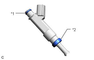
| *1 | O-ring |
| *2 | Injector Vibration Insulator |
Apply a light coat of gasoline or spindle oil to new injector vibration insulators and new O-rings, and then install one to each fuel injector assembly.
Apply a light coat of gasoline or spindle oil where the fuel delivery pipe sub-assembly contacts each O-ring.
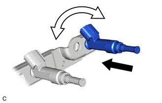

|
Push |

|
Turn |
While turning the fuel injector assembly left and right, install it to the fuel delivery pipe sub-assembly.
- NOTICE:
- ·
Do not damage the fuel injector assembly or O-ring.
·Make sure that the O-ring is not twisted or moved out of place when installing the fuel injector assembly.
·After installing each fuel injector assembly, check that it turns smoothly. If not, replace the O-ring with a new one.
- HINT:
-
Use the same procedure to install the other fuel injector assemblies.
23807V
2.INSTALL NO. 1 DELIVERY PIPE SPACER
- NOTICE:
-
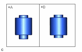 0.271,0.167 3.146,1.958 2.875,1.792 1.646,1.958 1.646,0.167 false 0.333,0.219 0.708,0.458 0.375,0.24 12 false *A 1.708,0.208 2.083,0.448 0.375,0.24 12 false *B
*A for Type A *B for Type B
-
Check the shape of the No. 1 delivery pipe spacer.
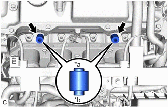
| *a | Fuel Delivery Pipe Sub-assembly Side |
| *b | Cylinder Head Sub-assembly Side |
for Type A:
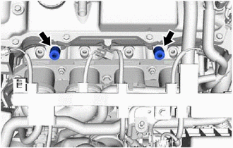
Install the 2 No. 1 delivery pipe spacers to the cylinder head sub-assembly.
- NOTICE:
-
Install the No. 1 delivery pipe spacers in the correct direction.
for Type B:
Install the 2 No. 1 delivery pipe spacers to the cylinder head sub-assembly.
23807
3.INSTALL FUEL DELIVERY PIPE SUB-ASSEMBLY
Install the fuel delivery pipe sub-assembly with the 4 fuel injector assemblies with the 2 bolts.
- Torque:
- 21 N*m (214 kgf*cm, 15 ft.*lbf)
- NOTICE:
- ·
Be careful not to drop the fuel injector assemblies when installing the fuel delivery pipe sub-assembly.
·Check that the fuel injector assemblies turn smoothly after installing the fuel delivery pipe sub-assembly.
Install the clamp of the fuel delivery pipe sub-assembly to the cylinder head sub-assembly with the bolt.
- Torque:
- 21 N*m (214 kgf*cm, 15 ft.*lbf)
23901
4.CONNECT FUEL TUBE SUB-ASSEMBLY
Connect the fuel tube sub-assembly to the fuel pipe.
Install the No. 1 fuel pipe clamp to the fuel tube connector and close the cover of the No. 1 fuel pipe clamp.
82121
5.CONNECT ENGINE WIRE
Engage the clamp to connect the engine wire.
Install the bolt.
- Torque:
- 8.0 N*m (82 kgf*cm, 71 in.*lbf)
Connect the 4 fuel injector assembly connectors.
12262
6.CONNECT NO. 2 VENTILATION HOSE
Connect the No. 2 ventilation hose to the cylinder head cover sub-assembly and slide the clip to secure it.
25601L
7.INSTALL EGR PIPE WITH COOLER SUB-ASSEMBLY
8.CONNECT CABLE TO NEGATIVE AUXILIARY BATTERY TERMINAL
9.INSPECT FOR FUEL LEAK
10.PERFORM INITIALIZATION
Perform "Inspection After Repair" after replacing a fuel injector assembly.
11. INITIALIZATION AFTER RECONNECTING AUXILIARY BATTERY TERMINAL
- HINT:
-
When disconnecting and reconnecting the auxiliary battery, there is an automatic learning function that completes learning when the respective system is used.