8ZR-FXE EMISSION CONTROL EGR COOLER INSTALLATION
PROCEDURE

 25601L
1.INSTALL EGR PIPE WITH COOLER SUB-ASSEMBLY
25601L
1.INSTALL EGR PIPE WITH COOLER SUB-ASSEMBLY
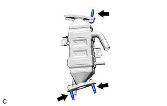
Using an E8 "TORX" socket wrench, install the 3 stud bolts to the EGR pipe with cooler sub-assembly.
- HINT:
-
If a stud bolt is deformed or the threads are damaged, replace it.
- Torque:
- 5.0 N*m (51 kgf*cm, 44 in.*lbf)
Install a new EGR valve gasket to the EGR valve assembly.
Install the EGR pipe with cooler sub-assembly to the EGR valve assembly with the 2 nuts.
- Torque:
- 21 N*m (214 kgf*cm, 15 ft.*lbf)
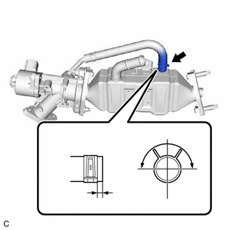
| *a | 0 to 4 mm (0 to 0.157 in.) |
| *b | LH |
| *c | Front of the vehicle |
| *d | 180° |
Connect the No. 6 water by-pass hose to the EGR pipe with cooler sub-assembly and slide the clip to secure it.
- HINT:
-
Engage the clip within the area shown in the illustration.
Install a new EGR cooler gasket to the EGR pipe with cooler sub-assembly.
Set the EGR pipe with cooler sub-assembly with the EGR valve assembly to the engine assembly.
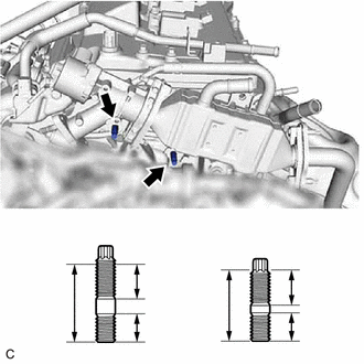
| *a | Stud Bolt (A) |
| *b | Stud Bolt (B) |
| *c | 48 mm (1.890 in.) |
| *d | 26 mm (1.024 in.) |
| *e | 13 mm (0.512 in.) |
| *f | 29 mm (1.142 in.) |
| *g | 14 mm (0.551 in.) |
| *h | 13 mm (0.512 in.) |
Using an E8 "TORX" socket wrench, install the stud bolt (A) and stud bolt (B) to the cylinder head sub-assembly and camshaft housing sub-assembly.
- HINT:
-
If a stud bolt is deformed or the threads are damaged, replace it.
- Torque:
- 9.5 N*m (97 kgf*cm, 84 in.*lbf)
Temporarily install the EGR pipe with cooler sub-assembly with the EGR valve assembly to the cylinder head sub-assembly and camshaft housing sub-assembly with the bolt and 2 nuts.
Temporarily install the EGR pipe with cooler sub-assembly to the exhaust manifold (TWC: Front Catalyst) with 2 new nuts.
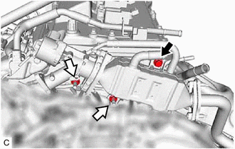

|
Bolt |

|
Nut |
Tighten the bolt and 2 nuts.
- Torque:
- 21 N*m (214 kgf*cm, 15 ft.*lbf)
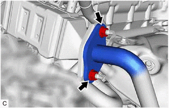
Tighten the 2 nuts.
- Torque:
- 26 N*m (265 kgf*cm, 19 ft.*lbf)
Connect the EGR valve assembly connector.
16281
2.CONNECT NO. 4 WATER BY-PASS HOSE
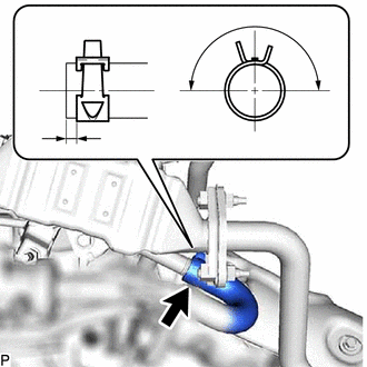
| *a | Up |
| *b | LH |
| *c | Paint Mark |
| *d | 180° |
| *e | 0 to 4 mm (0 to 0.157 in.) |
Type A:
Connect the No. 4 water by-pass hose to the EGR pipe with cooler sub-assembly and slide the clip to secure it.
- HINT:
-
Engage the clip within the area shown in the illustration.
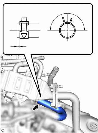
| *a | Up |
| *b | LH |
| *c | Paint Mark |
| *d | 180° |
| *e | 0 to 4 mm (0 to 0.157 in.) |
Type B:
Connect the No. 4 water by-pass hose to the EGR pipe with cooler sub-assembly and slide the clip to secure it.
- HINT:
-
Engage the clip within the area shown in the illustration.
87245W
3.CONNECT INLET HEATER WATER HOSE
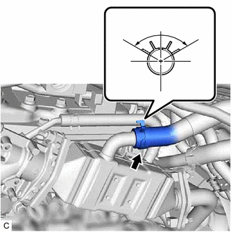
| *a | Up |
| *b | LH |
| *c | Paint Mark |
| *d | 120° |
Connect the inlet heater water hose to the EGR pipe with cooler sub-assembly and slide the clip to secure it.
- HINT:
-
Engage the clip within the area shown in the illustration.
16261
4.CONNECT WATER BY-PASS HOSE
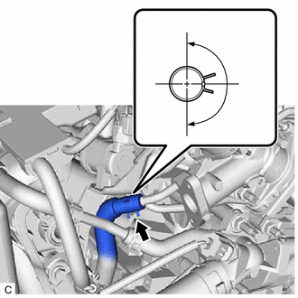
| *a | Up |
| *b | LH |
| *c | Paint Mark |
| *d | 180° |
Connect the water by-pass hose to the EGR valve assembly and slide the clip to secure it.
- HINT:
-
Engage the clip within the area shown in the illustration.
25610
5.INSTALL EGR PIPE ASSEMBLY
G9200
6.INSTALL INVERTER WITH CONVERTER ASSEMBLY