LIGHTING (INT) LIGHTING SYSTEM(except NR Series Engine) Ambient Illumination Light Circuit
DESCRIPTION
The main body ECU (multiplex network body ECU) controls the operation of the following lights:
Center Tray Illumination Light (Instrument Panel Light Assembly)
Cup Holder Light (Console Box Pocket Garnish)
Footwell Light LH (No. 1 Interior Illumination Light Assembly)
Footwell Light RH (No. 1 Interior Illumination Light Assembly)
WIRING DIAGRAM
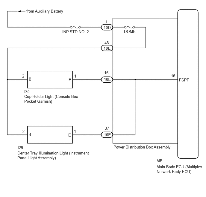
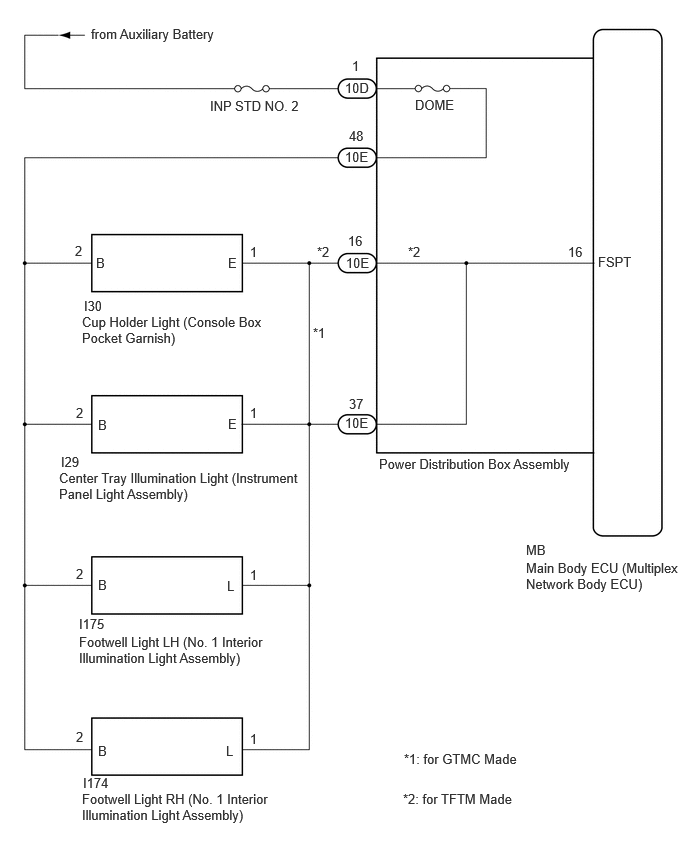
CAUTION / NOTICE / HINT
- NOTICE:
- ·
Inspect the fuses for circuits related to this system before performing the following procedure.
·Before replacing the main body ECU (multiplex network body ECU), refer to Service Bulletin.
PROCEDURE
Perform the Active Test according to the display on the GTS.
- Body Electrical > Main Body > Active Test
-
Tester Display Measurement Item Control Range Diagnostic Note Front Footwell Lights Turns on the following lights:
·Center tray illumination light*1
·Cup holder light*2
·Footwell light LH*3
·Footwell light RH*3
OFF or ON Perform the Active Test with the vehicle stopped and ignition switch ON.
*1: w/ Center tray illumination light
*2: w/ Cup holder light
*3: w/ Footwell light
- Body Electrical > Main Body > Active Test
-
Tester Display Front Footwell Lights - 50004 449 22
- OK:
Center tray illumination light and cup holder light come on.
- Result:
Result Proceed to OK A NG (Center tray illumination light does not come on) B NG (Cup holder light does not come on) C NG (Footwell light LH does not come on) D NG (Footwell light RH does not come on) E NG (Center tray illumination light, cup holder light, footwell light LH and footwell light RH does not come on) F
A
B
C
D
E
F
Inspect the center tray illumination light (instrument panel light assembly).
- Result:
Proceed to OK NG
OK
NG
Disconnect the 10E power distribution box assembly connector.
Measure the resistance according to the value(s) in the table below.
- Standard Resistance (w/o Footwell Light):
Tester Connection Condition Specified Condition I29-2 (B) - 10E-48 Always Below 1 Ω I29-1 (E) - 10E-37 Always Below 1 Ω I29-2 (B) or 10E-48 - Body ground Always 10 kΩ or higher I29-1 (E) or 10E-37 - Body ground Always 10 kΩ or higher
- Standard Resistance (for GTMC Made with Footwell Light):
Tester Connection Condition Specified Condition I29-2 (B) - 10E-48 Always Below 1 Ω I29-1 (E) - 10E-37 Always Below 1 Ω I29-2 (B) or 10E-48 - Body ground Always 10 kΩ or higher I29-1 (E) or 10E-37 - Body ground Always 10 kΩ or higher
- Standard Resistance (for TFTM Made with Footwell Light):
Tester Connection Condition Specified Condition I29-2 (B) - 10E-48 Always Below 1 Ω I29-1 (E) - 10E-37 Always Below 1 Ω I29-2 (B) or 10E-48 - Body ground Always 10 kΩ or higher I29-1 (E) or 10E-37 - Body ground Always 10 kΩ or higher
- Result:
Proceed to OK NG
OK
NG
Inspect the cup holder light (console box pocket garnish).
- Result:
Proceed to OK NG
OK
NG
Disconnect the 10E power distribution box assembly connector.
Measure the resistance according to the value(s) in the table below.
- Standard Resistance (w/o Footwell Light, for TFTM Made with Footwell Light):
Tester Connection Condition Specified Condition I30-2 (B) - 10E-48 Always Below 1 Ω I30-1 (E) - 10E-16 Always Below 1 Ω I30-2 (B) or 10E-48 - Body ground Always 10 kΩ or higher I30-1 (E) or 10E-16 - Body ground Always 10 kΩ or higher
- Standard Resistance (for GTMC Made with Footwell Light):
Tester Connection Condition Specified Condition I30-2 (B) - 10E-48 Always Below 1 Ω I30-1 (E) - 10E-37 Always Below 1 Ω I30-2 (B) or 10E-48 - Body ground Always 10 kΩ or higher I30-1 (E) or 10E-37 - Body ground Always 10 kΩ or higher
- Result:
Proceed to OK NG
OK
NG
Inspect the footwell light LH (No. 1 interior illumination light assembly).
- Result:
Proceed to OK NG
OK
NG
Disconnect the 10E power distribution box assembly connector.
Measure the resistance according to the value(s) in the table below.
- Standard Resistance:
Tester Connection Condition Specified Condition I175-2 (B) - 10E-48 Always Below 1 Ω I175-1 (L) - 10E-37 Always Below 1 Ω I175-2 (B) or 10E-48 - Body ground Always 10 kΩ or higher I175-1 (L) or 10E-37 - Body ground Always 10 kΩ or higher
- Result:
Proceed to OK NG
OK
NG
Inspect the footwell light RH (No. 1 interior illumination light assembly).
- Result:
Proceed to OK NG
OK
NG
Disconnect the 10E power distribution box assembly connector.
Measure the resistance according to the value(s) in the table below.
- Standard Resistance:
Tester Connection Condition Specified Condition I174-2 (B) - 10E-48 Always Below 1 Ω I174-1 (L) - 10E-37 Always Below 1 Ω I174-2 (B) or 10E-48 - Body ground Always 10 kΩ or higher I174-1 (L) or 10E-37 - Body ground Always 10 kΩ or higher
- Result:
Proceed to OK NG
OK
NG
Disconnect the 10D power distribution box assembly connector.
Measure the voltage according to the value(s) in the table below.
- Standard Voltage:
Tester Connection Condition Specified Condition 10D-1 - Body ground Always 11 to 14 V
- Result:
Proceed to OK NG
OK
NG
Disconnect the 10E power distribution box assembly connector.
Disconnect the I29 center tray illumination light (instrument panel light assembly) connector.
Disconnect the I30 cup holder light (console box pocket garnish) connector.
Disconnect the I175 footwell light LH (No. 1 interior illumination light assembly) connector.
Disconnect the I174 footwell light RH (No. 1 interior illumination light assembly) connector.
Measure the resistance according to the value(s) in the table below.
- Standard Resistance (w/o Footwell Light):
Tester Connection Condition Specified Condition 10E-48 - I29-2 (B) Always Below 1 Ω 10E-48 or I29-2 (B) - Body ground Always 10 kΩ or higher 10E-48 - I30-2 (B) Always Below 1 Ω 10E-48 or I30-2 (B) - Body ground Always 10 kΩ or higher 10E-37 - I29-1 (E) Always Below 1 Ω 10E-37 or I29-1 (E) - Body ground Always 10 kΩ or higher 10E-16 - I30-1 (E) Always Below 1 Ω 10E-16 or I30-1 (E) - Body ground Always 10 kΩ or higher
- Standard Resistance (for GTMC Made with Footwell Light):
Tester Connection Condition Specified Condition 10E-48 - I29-2 (B) Always Below 1 Ω 10E-48 or I29-2 (B) - Body ground Always 10 kΩ or higher 10E-48 - I30-2 (B) Always Below 1 Ω 10E-48 or I30-2 (B) - Body ground Always 10 kΩ or higher 10E-48 - I175-2 (B) Always Below 1 Ω 10E-48 or I175-2 (B) - Body ground Always 10 kΩ or higher 10E-48 - I174-2 (B) Always Below 1 Ω 10E-48 or I174-2 (B) - Body ground Always 10 kΩ or higher 10E-37 - I29-1 (E) Always Below 1 Ω 10E-37 or I29-1 (E) - Body ground Always 10 kΩ or higher 10E-37 - I30-1 (E) Always Below 1 Ω 10E-37 or I30-1 (E) - Body ground Always 10 kΩ or higher 10E-37 - I175-1 (L) Always Below 1 Ω 10E-37 or I175-1 (L) - Body ground Always 10 kΩ or higher 10E-37 - I174-1 (L) Always Below 1 Ω 10E-37 or I174-1 (L) - Body ground Always 10 kΩ or higher
- Standard Resistance (for TFTM Made with Footwell Light):
Tester Connection Condition Specified Condition 10E-48 - I29-2 (B) Always Below 1 Ω 10E-48 or I29-2 (B) - Body ground Always 10 kΩ or higher 10E-48 - I30-2 (B) Always Below 1 Ω 10E-48 or I30-2 (B) - Body ground Always 10 kΩ or higher 10E-48 - I175-2 (B) Always Below 1 Ω 10E-48 or I175-2 (B) - Body ground Always 10 kΩ or higher 10E-48 - I174-2 (B) Always Below 1 Ω 10E-48 or I174-2 (B) - Body ground Always 10 kΩ or higher 10E-37 - I29-1 (E) Always Below 1 Ω 10E-37 or I29-1 (E) - Body ground Always 10 kΩ or higher 10E-16 - I30-1 (E) Always Below 1 Ω 10E-16 or I30-1 (E) - Body ground Always 10 kΩ or higher 10E-37 - I175-1 (L) Always Below 1 Ω 10E-37 or I175-1 (L) - Body ground Always 10 kΩ or higher 10E-37 - I174-1 (L) Always Below 1 Ω 10E-37 or I174-1 (L) - Body ground Always 10 kΩ or higher
- Result:
Proceed to OK NG
OK
NG
Disconnect the 10E power distribution box assembly connector.
Measure the resistance according to the value(s) in the table below.
- Standard Resistance:
Tester Connection Condition Specified Condition 10D-1 - 10E-48 Always Below 1 Ω
- Result:
Proceed to OK NG
OK
NG
Remove the main body ECU (multiplex network body ECU) from the power distribution box assembly.
Measure the resistance according to the value(s) in the table below.
- Standard Resistance (w/o Footwell Light):
Tester Connection Condition Specified Condition 10E-16 - MB-16 (FSPT) Always Below 1 Ω 10E-37 - MB-16 (FSPT) Always Below 1 Ω
- Standard Resistance (for GTMC Made with Footwell Light):
Tester Connection Condition Specified Condition 10E-16 - MB-16 (FSPT) Always Below 1 Ω
- Standard Resistance (for TFTM Made with Footwell Light):
Tester Connection Condition Specified Condition 10E-16 - MB-16 (FSPT) Always Below 1 Ω 10E-37 - MB-16 (FSPT) Always Below 1 Ω
- Result:
Proceed to OK NG
OK
NG