LIGHTING (EXT) LIGHTING SYSTEM(except NR Series Engine) TERMINALS OF ECU
CHECK MAIN BODY ECU (MULTIPLEX NETWORK BODY ECU) AND POWER DISTRIBUTION BOX ASSEMBLY
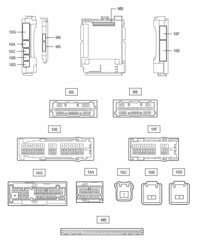
Disconnect the power distribution box assembly and main body ECU (multiplex network body ECU) connectors.
Measure the voltage and resistance according to the value(s) in the table below.
| Terminal No. (Symbol) | Terminal Description | Condition | Specified Condition |
|---|---|---|---|
| MB-13 (GND1) - Body ground | Ground | Always | Below 1 Ω |
| MB-14 (GND2) - Body ground | Ground | Always | Below 1 Ω |
| MB-26 (BECU) - Body ground | Auxiliary battery power supply | Ignition switch off | 11 to 14 V |
| MB-27 (IGR) - Body ground | Ignition power supply (IG signal) | Ignition switch ON | 11 to 14 V |
| Ignition switch off | Below 1 V |
Connect the power distribution box assembly and main body ECU (multiplex network body ECU) connectors.
Measure the voltage and check for pulses according to the value(s) in the table below.
| Terminal No. (Symbol) | Terminal Description | Condition | Specified Condition |
|---|---|---|---|
| 10F-27 - Body ground*1 | R shift position switch signal | Ignition switch off, reverse (R) not selected | Below 1 V |
| Ignition switch ON, reverse (R) selected | 11 to 14 V | ||
| 10A-17 - Body ground*2 | R shift position switch signal | Ignition switch off, reverse (R) not selected | Below 1 V |
| Ignition switch ON, reverse (R) selected | 11 to 14 V | ||
| 10A-2 - Body ground | Daytime running light system drive output | Daytime running light system operating | Below 1 V |
| Daytime running light system not operating | 11 to 14 V | ||
| 10A-3 - Body ground | H-LP LH relay drive output | ·
15 seconds or more after ignition switch turned off ·
Taillights off |
9.5 to 14 V |
·
Ignition switch ON or within 15 seconds after ignition switch turned off ·
Taillights on |
Below 1 V | ||
| 10A-4 - Body ground | H-LP RH relay drive output | ·
15 seconds or more after ignition switch turned off ·
Taillights off |
9.5 to 14 V |
·
Ignition switch ON or within 15 seconds after ignition switch turned off ·
Taillights on |
Below 1 V | ||
| 10A-20 - Body ground | Clearance lights drive output | Taillights on | 11 to 14 V |
| Taillight off | Below 1 V | ||
| 10G-7 - Body ground*3 | Front fog lights drive output | Taillights on, fog light switch in off position | 11 to 14 V |
| Taillights on, fog light switch in front position | Below 1 V | ||
| 10G-13 - Body ground | Back-up lights drive output | Ignition switch off, reverse (R) not selected | Below 1 V |
| Ignition switch ON, reverse (R) selected | 11 to 14 V | ||
| 10G-15 - Body ground | Taillights drive output | Taillights off | Below 1 V |
| Taillights on | 11 to 14 V | ||
| 10G-29 - Body ground | Rear fog light drive output | Taillights on, fog light switch in off position | Below 1 V |
| Taillights on, fog light switch in rear position | 11 to 14 V | ||
| I85-8 (CLTB) - I85-21 (CLTE) | Automatic light control sensor power supply output | Ignition switch ON | 11 to 14 V |
| I85-14 (AHBI) - Body ground | Auto high beam switch signal input | Auto high beam switch off | 11 to 14 V |
| Auto high beam switch on | Below 1 V | ||
| I85-15 (AHID) - Body ground | Auto high beam switch indicator drive output | Ignition switch ON, auto high beam switch off | 11 to 14 V |
| Ignition switch ON, auto high beam switch on | Below 1 V | ||
| I85-20 (CLTS) - Body ground | Automatic light control sensor signal input | Ignition switch off | Below 1 V |
| Ignition switch ON | Pulse generation (See waveform 1) | ||
| I85-22 (DIM) - Body ground | High beam headlight drive output | Light control switch in head position and dimmer switch in high or high flash position | Below 1 V |
| Dimmer switch not in high or high flash position | 11 to 14 V | ||
| I85-26 (HEAD) - Body ground | Light control switch head position input | Light control switch not in head position | 11 to 14 V |
| Light control switch in head position | Below 1 V |
*1: for HV Model
*2: for Gasoline Model
*3: w/ Front Fog Light
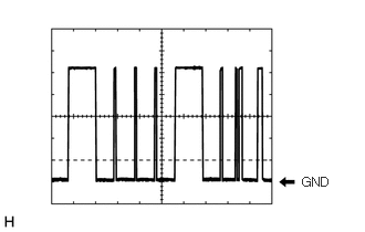
Waveform 1
| Item | Content |
|---|---|
| Tester Connection | I85-20 (CLTS) - Body ground |
| Tool setting | 2 V/DIV., 10 ms./DIV. |
| Condition | Ignition switch ON |
- HINT:
-
The communication waveform changes according to the surrounding brightness.
CHECK COMBINATION METER ASSEMBLY
for 12.3 Inch Display: Click hereVehicle Interior>METER / GAUGE / DISPLAY>METER / GAUGE SYSTEM (for 12.3 Inch Display)>TERMINALS OF ECU202304,202307,_58,_080793,_0473175,RM100000002B5WF,202307,202406,_58,_080793,_0473175,RM100000002D0F5,202406,999999,_58,_080793,_0473175,RM100000002NEI0,
except 12.3 Inch Display: Click hereVehicle Interior>METER / GAUGE / DISPLAY>METER / GAUGE SYSTEM (except 12.3 Inch Display)>TERMINALS OF ECU202304,202307,_58,_080793,_0598151,RM100000002B2XC,202307,202406,_58,_080793,_0598151,RM100000002D0G4,202406,202502,_58,_080793,_0598151,RM100000002NEI1,202502,999999,_58,_080793,_0598151,RM100000002RNOV,
CHECK STEERING SENSOR
for Gasoline Model: Click herePower Source / Network>NETWORKING>CAN COMMUNICATION SYSTEM (for Gasoline Model (except NR Series))>TERMINALS OF ECU202304,202406,_57,_080743,_0598531,RM100000002BFVB,202406,999999,_57,_080743,_0598531,RM100000002N77A,
CHECK HYBRID VEHICLE CONTROL ECU (for HV Model)
ECM (for Gasoline Model)
for M15B-FKS: Click hereEngine / Hybrid System>M15B-FKS (ENGINE CONTROL)>SFI SYSTEM>TERMINALS OF ECM202304,999999,_51,_096196,_0456237,RM100000002BK2I,
for M15C-FKS: Click hereEngine / Hybrid System>M15C-FKS (ENGINE CONTROL)>SFI SYSTEM>TERMINALS OF ECM202304,999999,_51,_096205,_0456238,RM100000002BK4Q,
for M20A-FKS: Click hereEngine / Hybrid System>M20A-FKS (ENGINE CONTROL)>SFI SYSTEM>TERMINALS OF ECM202304,999999,_51,_101144,_0469422,RM100000002BK8H,
for M20C-FKS: Click hereEngine / Hybrid System>M20C-FKS (ENGINE CONTROL)>SFI SYSTEM>TERMINALS OF ECM202304,999999,_51,_105190,_0484152,RM100000002BK8I,
for M20E-FKS: Click hereEngine / Hybrid System>M20E-FKS (ENGINE CONTROL)>SFI SYSTEM>TERMINALS OF ECM202304,999999,_51,_101153,_0478272,RM100000002BK8J,