8ZR-FXE ENGINE MECHANICAL ENGINE ASSEMBLY INSTALLATION
CAUTION / NOTICE / HINT
- CAUTION:
-
The engine assembly with transaxle is very heavy. Be sure to follow the procedure described in the repair manual, or the engine lifter may suddenly drop.
- HINT:
-
Perform "Inspection After Repair" after replacing the engine assembly.
PROCEDURE

 1.INSTALL ENGINE HANGERS
2.REMOVE ENGINE ASSEMBLY FROM ENGINE STAND
Remove the engine assembly from the engine stand.
13405
3.INSTALL FLYWHEEL SUB-ASSEMBLY
31270
4.INSTALL TRANSMISSION INPUT DAMPER ASSEMBLY
5.INSTALL ENGINE ASSEMBLY
82121
6.INSTALL ENGINE WIRE
Connect all the connectors and clamps, and install the engine wire to the engine assembly with transaxle.
11363A
7.INSTALL FLYWHEEL HOUSING SIDE COVER
28193
8.INSTALL STARTER HOLE INSULATOR
88370
9.INSTALL COMPRESSOR WITH MOTOR ASSEMBLY
12305
10.INSTALL ENGINE MOUNTING INSULATOR SUB-ASSEMBLY RH
- HINT:
-
Perform this procedure only when replacement of the engine mounting insulator sub-assembly RH is necessary.
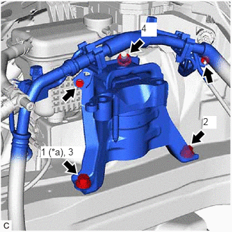
| *a | Temporarily Tighten |
Temporarily install the engine mounting insulator sub-assembly RH to the vehicle.
Install the 2 bolts and nut in the order shown in the illustration.
- Torque:
- 72 N*m (734 kgf*cm, 53 ft.*lbf)
Connect the air conditioner tube and accessory assembly to the engine mounting insulator sub-assembly RH with the bolt and nut.
- Torque:
- 9.8 N*m (100 kgf*cm, 87 in.*lbf)
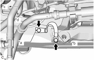
| *a | Mark |
| *b | Contact Point to Stop Rotation When Tightening |
| *c | Front of Vehicle |
| *d | LH Side |
Install the No. 2 earth wire to the engine mounting insulator sub-assembly RH and vehicle body with the 2 bolts as shown in the illustration.
- Torque:
- 10.5 N*m (107 kgf*cm, 8 ft.*lbf)
- NOTICE:
-
Make sure that the mark is facing the front of the vehicle.
12372A
11.INSTALL ENGINE MOUNTING INSULATOR LH
- HINT:
-
Perform this procedure only when replacement of the engine mounting insulator LH is necessary.
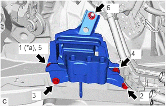
| *a | Temporarily Tighten |
Temporarily install the engine mounting insulator LH to the vehicle.
Install the 4 bolts and nut in the order shown in the illustration.
- Torque:
- 42 N*m (428 kgf*cm, 31 ft.*lbf)
Engage the 2 clamps.
12.REMOVE ENGINE HANGER
13.INSTALL WIRE HARNESS CLAMP BRACKET
Install the wire harness clamp bracket with the bolt.
- Torque:
- 39 N*m (398 kgf*cm, 29 ft.*lbf)
Engage the 3 clamps.
14.INSTALL ENGINE ASSEMBLY WITH TRANSAXLE
Using height adjustment attachments and plate lift attachments to keep the engine assembly with transaxle and front suspension crossmember sub-assembly level, set an engine lifter underneath the engine assembly with transaxle and front suspension crossmember sub-assembly.
- NOTICE:
- ·
Using height adjustment attachments and plate lift attachments, keep the engine assembly with transaxle horizontal.
·Do not perform any procedures while the engine assembly is suspended because doing so may cause the engine assembly to drop, resulting in injury. However, the engine assembly needs to be suspended when it is installed to or removed from an engine stand.
·To prevent the oil pan sub-assembly from deforming, do not place any attachments under the oil pan sub-assembly of the engine assembly with transaxle.
Operate the engine lifter and install the engine assembly with transaxle to the vehicle.
- CAUTION:
-
Do not raise the engine assembly with transaxle more than necessary. If the engine is raised excessively, the vehicle may also be lifted up.
- NOTICE:
- ·
Make sure that the engine assembly with transaxle is clear of all wiring and hoses.
·While raising the engine assembly with transaxle into the vehicle, do not allow it to contact the vehicle.
Connect the front suspension crossmember sub-assembly to the vehicle with the 4 bolts.
- Torque:
- 141 N*m (1438 kgf*cm, 104 ft.*lbf)
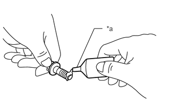
| *a | Adhesive |
Apply adhesive to 2 or 3 threads of the bolt.
- Adhesive:
Toyota Genuine Adhesive 1324, Three Bond 1324 or equivalent
Install the No. 2 engine mounting stay LH with the bolt.
- Torque:
- 8.0 N*m (82 kgf*cm, 71 in.*lbf)
Install the engine mounting insulator LH to the hybrid vehicle transaxle assembly with the 3 bolts and nut.
- Torque:
- Bolt : 70 N*m (714 kgf*cm, 52 ft.*lbf)
- Nut : 20 N*m (204 kgf*cm, 15 ft.*lbf)
Install the engine mounting insulator sub-assembly RH to the engine mounting bracket RH with the 2 bolts and nut.
- Torque:
- Bolt : 72 N*m (734 kgf*cm, 53 ft.*lbf)
- Nut : 41 N*m (418 kgf*cm, 30 ft.*lbf)
51108A
15.INSTALL REAR SIDE RAIL REINFORCEMENT SUB-ASSEMBLY LH
51107A
16.INSTALL REAR SIDE RAIL REINFORCEMENT SUB-ASSEMBLY RH
- HINT:
-
Use the same procedure as for the LH side.
17.INSTALL FRONT DRIVE SHAFT ASSEMBLY
17410
18.INSTALL FRONT EXHAUST PIPE ASSEMBLY
57533B
19.INSTALL FRONT FLOOR CENTER BRACE
58166A
20.INSTALL FRONT FLOOR COVER LH
58165C
21.INSTALL FRONT FLOOR COVER RH
- HINT:
-
Use the same procedure as for the LH side.
45025D
22.CONNECT NO. 1 STEERING COLUMN HOLE COVER SUB-ASSEMBLY
45260
23.CONNECT NO. 2 STEERING INTERMEDIATE SHAFT ASSEMBLY
45259A
24.INSTALL COLUMN HOLE COVER SILENCER SHEET
82127D
25.CONNECT NO. 7 ENGINE WIRE
Connect the No. 7 engine wire to the hybrid vehicle transaxle assembly with the bolt.
- Torque:
- 20 N*m (204 kgf*cm, 15 ft.*lbf)
Engage the 2 clamps.
88704
26.CONNECT SUCTION HOSE SUB-ASSEMBLY
88703
27.CONNECT DISCHARGE HOSE SUB-ASSEMBLY
23901
28.CONNECT FUEL TUBE SUB-ASSEMBLY
23829A
29.CONNECT FUEL VAPOR FEED HOSE
Connect the fuel vapor feed hose to the fuel vapor feed pipe and slide the clip to secure it.
87246
30.CONNECT OUTLET HEATER WATER HOSE
Connect the outlet heater water hose.
87245
31.CONNECT INLET HEATER WATER HOSE
Connect the inlet heater water hose.
16572D
32.CONNECT NO. 2 RADIATOR HOSE
Connect the No. 2 radiator hose to the water inlet sub-assembly and slide the clip to secure it.
16571C
33.CONNECT NO. 1 RADIATOR HOSE
Connect the No. 1 radiator hose to the water outlet and slide the clip to secure it.
33820B
34.CONNECT TRANSMISSION CONTROL CABLE ASSEMBLY
Connect the transmission control cable assembly to the engine assembly with the bolt.
- Torque:
- 12 N*m (122 kgf*cm, 9 ft.*lbf)
Connect the transmission control cable assembly to the transmission control cable support.
Connect the transmission control cable assembly to the No. 1 transmission control cable bracket with a new clip.
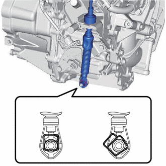
| *a | Correct |
| *b | Incorrect |
Connect the transmission control cable assembly to the transmission control shaft lever as shown in the illustration.
G9200
35.INSTALL INVERTER WITH CONVERTER ASSEMBLY
17751
36.INSTALL INLET NO. 1 AIR CLEANER
17771A
37.INSTALL AIR CLEANER BRACKET
17701
38.INSTALL AIR CLEANER CASE SUB-ASSEMBLY
17801
39.INSTALL AIR CLEANER FILTER ELEMENT SUB-ASSEMBLY
22210
40.INSTALL THROTTLE BODY ASSEMBLY
17752
41.INSTALL INLET NO. 2 AIR CLEANER
53289A
42.INSTALL RADIATOR SUPPORT OPENING COVER
16296
43.CONNECT NO. 8 WATER BY-PASS HOSE
Connect the No. 8 water by-pass hose to the No. 4 water by-pass hose and slide the clip to secure it.
44.ADD ENGINE OIL
45.ADD HYBRID TRANSAXLE FLUID
46.ADD ENGINE COOLANT (for Engine)
47.CHARGE AIR CONDITIONING SYSTEM WITH REFRIGERANT
48.CHECK ENGINE OIL LEVEL
49.INSPECT HYBRID TRANSAXLE FLUID
50.INSPECT SHIFT LEVER POSITION
51.ADJUST SHIFT LEVER POSITION
52.INSPECT FOR COOLANT LEAK (for Inverter)
53.INSPECT FOR COOLANT LEAK (for Engine)
54.WARM UP COMPRESSOR
55.INSPECT FOR REFRIGERANT LEAK
56.INSPECT FOR FUEL LEAK
57.INSPECT FOR OIL LEAK
58.INSPECT FOR EXHAUST GAS LEAK
51444A
59.INSTALL REAR ENGINE UNDER COVER LH
Install the rear engine under cover LH to the vehicle with the 4 clips.
Install the screw.
51443C
60.INSTALL REAR ENGINE UNDER COVER RH
Install the rear engine under cover RH to the vehicle with the 4 clips.
Install the screw.
51410
61.INSTALL NO. 1 ENGINE UNDER COVER ASSEMBLY
Install the No. 1 engine under cover assembly to the vehicle with the 10 clips.
Install the 4 bolts.
- Torque:
- 7.5 N*m (76 kgf*cm, 66 in.*lbf)
62.INSTALL FRONT WHEELS
63.INSPECT IGNITION TIMING
64.INSPECT ENGINE IDLE SPEED
65.INSPECT CO/HC
66.INSPECT AND ADJUST FRONT WHEEL ALIGNMENT