HYBRID / BATTERY CONTROL 8ZR-FXE INVERTER WITH CONVERTER INSTALLATION
PROCEDURE

 G9200
1.SET INVERTER WITH CONVERTER ASSEMBLY
G9200
1.SET INVERTER WITH CONVERTER ASSEMBLY
- CAUTION:
-
Be sure to wear insulated gloves.
Temporarily install the inverter with converter assembly.
- NOTICE:
- ·
When installing the inverter with converter assembly, be careful not to damage the parts around it.
·To prevent damage, do not hold the inverter with converter assembly by the connectors, brackets or cooling pipes.
·To prevent damage due to static electricity, do not touch the terminals of the disconnected connectors.
·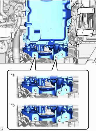 0.396,2.594 0.594,2.802 0.198,0.208 10 true *a 0.396,3.667 0.594,3.875 0.198,0.208 10 true *b
*a Correct *b Incorrect
Make sure that the inverter with converter assembly is positioned so that the stud bolts are in contact with the base of the U-shaped portions of the No. 1 inverter bracket.
G1148
2.CONNECT MOTOR CABLE
- CAUTION:
-
Be sure to wear insulated gloves.
- NOTICE:
-
Do not allow any foreign matter or water to enter the inverter with converter assembly.
Temporarily connect the motor cable to the inverter with converter assembly with the 4 bolts.
- NOTICE:
- ·
Do not touch the waterproof seal or terminals of the connector.
·Do not damage the terminals, connector housing or inverter with converter assembly during connection.
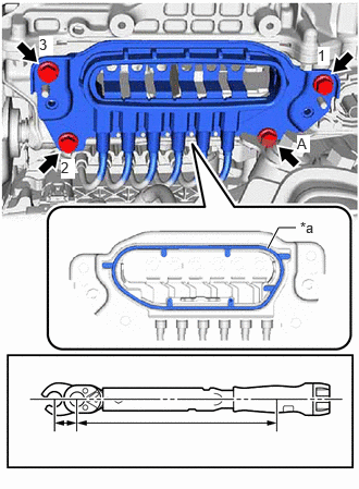
| *a | Waterproof Seal |
| *b | 10 mm Union Nut Wrench Fulcrum Length |
| *c | Torque Wrench Fulcrum Length |
Fully tighten the 3 bolts in the order shown in the illustration.
- Torque:
- 8.0 N*m (82 kgf*cm, 71 in.*lbf)
Using a 10 mm union nut wrench, fully tighten the bolt (A).
- Torque:
- Specified tightening torque : 8.0 N*m (82 kgf*cm, 6 ft.*lbf)
- HINT:
- ·
Calculate the torque wrench reading when changing the fulcrum length of the torque wrench.
·When using 10 mm union nut wrench (fulcrum length of 22 mm (0.866 in.)) + torque wrench (fulcrum length of 162 mm (6.38 in.)):
7.0 N*m (71 kgf*cm, 62 in.*lbf)
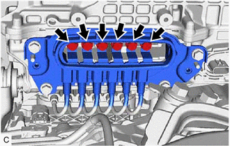
Temporarily install the 6 bolts.
- CAUTION:
-
Insulate the tool with insulating tape.
- NOTICE:
- ·
To prevent the threads from being damaged, temporarily tighten the 6 bolts by hand.
·Do not damage the terminals, connector housing or inverter with converter assembly during connection.
Fully tighten the 6 bolts.
- Torque:
- 8.0 N*m (82 kgf*cm, 71 in.*lbf)
- CAUTION:
-
Insulate the tool with insulating tape.
- NOTICE:
- ·
Do not damage the terminals, connector housing or inverter with converter assembly during connection.
·Be sure to use a torque wrench to tighten the bolts.
G9221
3.INSTALL INVERTER COVER
- CAUTION:
-
Be sure to wear insulated gloves.
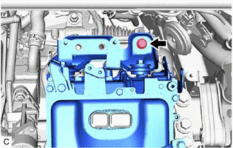
To prevent the inverter with converter assembly from falling, temporarily install the bolt in the location shown in the illustration.
Shift the position of the inverter with converter assembly and temporarily set it on top of the stud bolts as shown in the illustration.
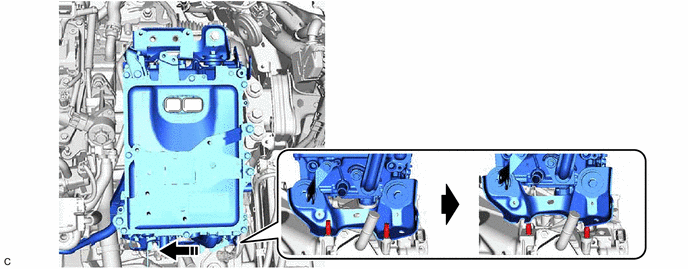
- NOTICE:
-
When lifting, make sure not to apply force to the motor cable.
Install the inverter cover to the inverter with converter assembly with the 2 bolts.
- Torque:
- 8.0 N*m (82 kgf*cm, 71 in.*lbf)
- NOTICE:
- ·
Visually confirm that the inverter cover waterproof seal is securely installed before installing the inverter cover.
·Do not touch the waterproof seal of the inverter cover.
·Make sure that the interlock is fully engaged.
·Do not damage the terminals, interlock connector or inverter with converter assembly during installation.
·Do not allow any foreign matter or water to enter the inverter with converter assembly.
·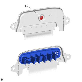 1.76,0.75 1.208,0.281 true 1.042,0.188 1.354,0.385 0.313,0.198 10 false *a
*a Screw
Do not remove or excessively tighten the screw of the inverter cover.
·Although the inverter cover may feel loose, this is not due to a malfunction.
· 1.813,1.833 2.031,2.01 0.219,0.177 10 true *a
*a No Gap
Push in the inverter cover until it contacts the inverter with converter assembly.
Shift the position of the inverter with converter assembly and temporarily set it on the hybrid vehicle transaxle assembly as shown in the illustration.
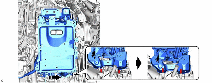
- NOTICE:
-
When lifting, make sure not to apply force to the motor cable.
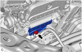
Install the inverter cover with the bolt to the hybrid vehicle transaxle assembly.
- Torque:
- 8.0 N・m (82 kgf・cm, )
G9200
4.INSTALL INVERTER WITH CONVERTER ASSEMBLY
- CAUTION:
-
Be sure to wear insulated gloves.
Temporarily install the inverter with converter assembly with the 5 bolts and 2 nuts.
- NOTICE:
- ·
When installing the inverter with converter assembly, be careful not to damage the parts around it.
·To prevent damage, do not hold the inverter with converter assembly by the connectors, brackets or cooling pipes.
·To prevent damage due to static electricity, do not touch the terminals of the disconnected connectors.
·
0.396,2.594 0.594,2.802 0.198,0.208 10 true *a 0.396,3.667 0.594,3.875 0.198,0.208 10 true *b*a Correct *b Incorrect
Make sure that the inverter with converter assembly is positioned so that the stud bolts are in contact with the base of the U-shaped portions of the No. 1 inverter bracket.
- HINT:
-
If the bolts and nuts are not tightened appropriately, the inverter with converter assembly may make an abnormal noise.
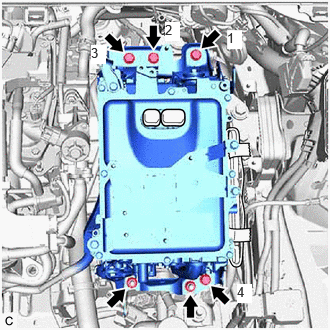
Fully tighten the 4 bolts in the order shown in the illustration.
- Torque:
- 55 N*m (561 kgf*cm, 41 ft.*lbf)
Fully tighten the 2 nuts.
- Torque:
- 55 N*m (561 kgf*cm, 41 ft.*lbf)
82121
5.CONNECT ENGINE WIRE
- CAUTION:
-
Be sure to wear insulated gloves.
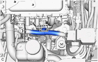
Engage the clamp and connect the engine wire to the inverter with converter assembly.
G922AA
6.CONNECT INLET NO. 1 INVERTER COOLING HOSE
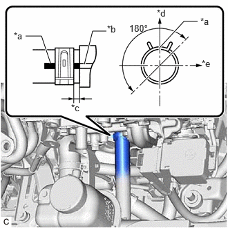
| *a | Alignment Mark |
| *b | Rib |
| *c | 2 to 11 mm (0.0787 to 0.4331 in.) |
| *d | Up |
| *e | LH Side |
Connect the inlet No. 1 inverter cooling hose to the inverter with converter assembly and slide the clip to secure it.
- NOTICE:
- ·
To prevent foreign matter from entering the inverter with converter assembly and inverter cooling system, do not remove the pieces of cloth from the pipe and disconnected hose until installation.
·Make sure to align the alignment mark of the hose with the alignment mark of the pipe of the inverter with converter assembly.
- HINT:
-
Make sure that the clip is positioned as shown in the illustration.
G922C
7.CONNECT OUTLET NO. 1 INVERTER COOLING HOSE
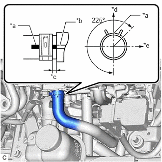
| *a | Alignment Mark |
| *b | Rib |
| *c | 2 to 11 mm (0.0787 to 0.4331 in.) |
| *d | Up |
| *e | LH Side |
Connect the outlet No. 1 inverter cooling hose to the inverter with converter assembly and slide the clip to secure it.
- NOTICE:
- ·
To prevent foreign matter from entering the inverter with converter assembly and inverter cooling system, do not remove the pieces of cloth from the pipe and disconnected hose until installation.
·Make sure to align the alignment mark of the hose with the rib of the inverter with converter assembly.
- HINT:
-
Make sure that the clip is positioned as shown in the illustration.
82127D
8.CONNECT NO. 7 ENGINE WIRE
- CAUTION:
-
Be sure to wear insulated gloves.
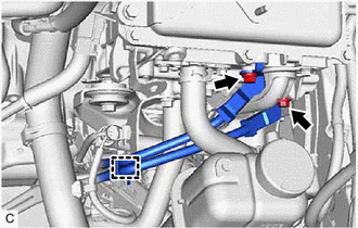
Engage the clamp.
Connect the No. 7 engine wire to the inverter with converter assembly with the 2 bolts.
- Torque:
- 10 N*m (102 kgf*cm, 89 in.*lbf)
82123
9.CONNECT NO. 3 ENGINE WIRE
Engage the clamp.
Engage the 2 claws to connect the engine wire to the No. 1 engine room relay block.
Install the nut.
- Torque:
- 8.35 N*m (85 kgf*cm, 74 in.*lbf)
821H1
10.CONNECT FLOOR UNDER WIRE
- CAUTION:
-
Be sure to wear insulated gloves.
Engage the clamps.
Connect the floor under wire to the inverter with converter assembly and install the 2 bolts.
- Torque:
- 8.0 N*m (82 kgf*cm, 71 in.*lbf)
- NOTICE:
- ·
Do not allow any foreign matter or water to enter the inverter with converter assembly.
·Do not touch the waterproof seal or terminals of the connector.
·Do not damage the terminals, connector housing or inverter with converter assembly when connecting the connector.
82111
11.CONNECT ENGINE ROOM MAIN WIRE
- CAUTION:
-
Be sure to wear insulated gloves.
- NOTICE:
-
Do not allow any foreign matter or water to enter the inverter with converter assembly.
Connect the inverter with converter assembly connector.
Engage the 3 clamps to connect the engine wire.
Connect the inverter with converter assembly connector.
- NOTICE:
- ·
To prevent damage due to static electricity, do not touch the terminals of the disconnected connectors.
·Do not damage the terminals, connector housing or inverter with converter assembly when connecting the connectors.
·Do not touch the waterproof seal or terminals of the connectors.
82121
12.CONNECT ENGINE WIRE
- CAUTION:
-
Be sure to wear insulated gloves.
- NOTICE:
-
Do not allow any foreign matter or water to enter the inverter with converter assembly.
Engage the 2 clamps to connect the engine wire.
Engage the clamp.
Install the 3 nuts.
- Torque:
- 8.0 N*m (82 kgf*cm, 71 in.*lbf)
Connect the inverter with converter assembly connector.
- NOTICE:
- ·
To prevent damage due to static electricity, do not touch the terminals of the disconnected connectors.
·Do not damage the terminals, connector housing or inverter with converter assembly when connecting the connectors.
·Do not touch the waterproof seal or terminals of the connectors.
Engage the 2 claws to connect the engine wire to the No. 1 engine room relay block.
Connect the 2 No. 1 engine room relay block connectors.
Install the No. 1 relay block cover to the No. 1 engine room relay block.
821H2
13.CONNECT HV AIR CONDITIONING WIRE
- CAUTION:
-
Be sure to wear insulated gloves.

| *a | Green-colored Lock |

|
Slide |
Engage the 2 clamps.
Connect the HV air conditioning wire connector and slide the green-colored lock as shown in the illustration to lock it securely.
- NOTICE:
-
Make sure that the connectors are connected securely.
17751
14.INSTALL INLET NO. 1 AIR CLEANER
17771A
15.INSTALL AIR CLEANER BRACKET
17701
16.INSTALL AIR CLEANER CASE SUB-ASSEMBLY
17801
17.INSTALL AIR CLEANER FILTER ELEMENT SUB-ASSEMBLY
17752
18.INSTALL INLET NO. 2 AIR CLEANER
53289A
19.INSTALL RADIATOR SUPPORT OPENING COVER
20.INSTALL AIR CLEANER HOSE ASSEMBLY
17705
21.INSTALL AIR CLEANER CAP SUB-ASSEMBLY
33822
22.CONNECT FLOOR SHIFT TRANSMISSION CONTROL SELECT CABLE
Install the nut to connect the floor shift transmission control select cable.
- Torque:
- 6.0 N*m (61 kgf*cm, 53 in.*lbf)
74404A
23.INSTALL BATTERY CLAMP SUB-ASSEMBLY
Install the battery clamp sub-assembly to the vehicle with the 3 bolts.
- Torque:
- 15.4 N*m (157 kgf*cm, 11 ft.*lbf)
G3834
24.INSTALL SERVICE PLUG GRIP
89661
25.INSTALL ECM
26.ADD COOLANT (for Inverter)
27.INSPECT FOR COOLANT LEAK (for Inverter)
28. PEFOME ECU CONFIGURATION
- HINT:
-
Perform this procedure only when replacement of the inverter with converter assembly.