8ZR-FXE ENGINE MECHANICAL CYLINDER HEAD GASKET INSTALLATION
PROCEDURE

 11115
1.INSTALL CYLINDER HEAD GASKET
11115
1.INSTALL CYLINDER HEAD GASKET
Remove any oil from the contact surfaces.
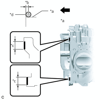
| *a | Cylinder Block Sub-assembly |
| *b | 3.0 to 5.0 mm (0.118 to 0.197 in.) |
| *c | 10 to 15 mm (0.394 to 0.591 in.) |
| *d | Diameter 7.0 to 9.0 mm (0.276 to 0.354 in.) |

|
Front of Engine |
Apply seal packing to the cylinder block sub-assembly as shown in the illustration.
- NOTICE:
-
Install the cylinder head gasket within 3 minutes and tighten the cylinder head set bolts within 15 minutes of applying seal packing.
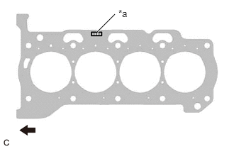
| *a | Lot No. |
|
|
Front of Engine |
Place a new cylinder head gasket on the cylinder block sub-assembly as shown in the illustration.
- NOTICE:
-
Make sure to install the cylinder head gasket in the correct direction.
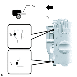
| *a | Cylinder Head Gasket |
| *b | Diameter 6 to 8 mm (0.236 to 0.315 in.) |
|
|
Front of Engine |
Apply seal packing to the cylinder head gasket as shown in the illustration.
11101
2.INSTALL CYLINDER HEAD SUB-ASSEMBLY
13716
3.INSTALL VALVE STEM CAP
13750
4.INSTALL VALVE LASH ADJUSTER ASSEMBLY
13801
5.INSTALL NO. 1 VALVE ROCKER ARM SUB-ASSEMBLY
11103
6.INSTALL CAMSHAFT HOUSING SUB-ASSEMBLY
13511
7.INSTALL CAMSHAFT
13512
8.INSTALL NO. 2 CAMSHAFT
9.INSTALL CAMSHAFT BEARING CAP
13523G
10.INSTALL CAMSHAFT TIMING SPROCKET
13050
11.INSTALL CAMSHAFT TIMING GEAR ASSEMBLY
12.SET NO. 1 CYLINDER TO TDC (COMPRESSION)
13506
13.INSTALL CHAIN SUB-ASSEMBLY
- HINT:
- ·
Be sure to install the chain sub-assembly with the mark plates facing away from the engine assembly.
·The mark plate on the camshaft side is colored orange.
·The mark plate on the crankshaft side is colored pink.
Temporarily install the crankshaft pulley set bolt to the crankshaft.
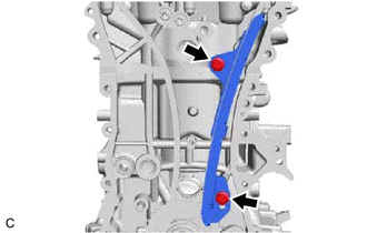
Install the No. 1 chain vibration damper to the cylinder head sub-assembly and cylinder block sub-assembly with the 2 bolts.
- Torque:
- 21 N*m (214 kgf*cm, 15 ft.*lbf)
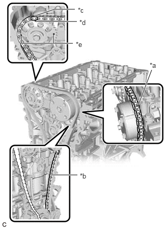
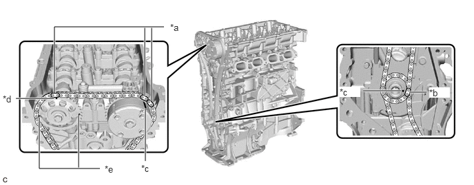
| *a | Place the chain sub-assembly on the sprocket |
| *b | Pass the chain sub-assembly through the damper |
| *c | Mark Plate (Orange) |
| *d | Timing Mark (Rectangle) |
| *e | Mark (Circle) |
Install the chain sub-assembly with the mark plates (orange) of the chain sub-assembly aligned with the timing mark (rectangle) as shown in the illustration.
- HINT:
- ·
There are 3 marks on the camshaft timing sprocket. Make sure to align the mark plate with the timing mark (rectangle).
·Do not pass the chain sub-assembly around the sprocket of the camshaft timing gear assembly. Only place it on the camshaft timing gear assembly.
·Pass the chain sub-assembly through the No. 1 chain vibration damper.
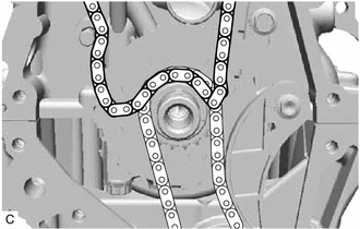
Place the chain sub-assembly on the crankshaft without passing it around the crankshaft.
Hold the hexagonal portion of the camshaft with a wrench and turn the camshaft timing gear assembly counterclockwise to align the mark plate (orange) with timing mark, and then install the chain sub-assembly.
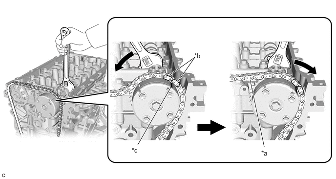
| *a | Tension the chain sub-assembly | *b | Mark Plate (Orange) |
| *c | Timing Mark | - | - |
- HINT:
-
If the camshaft timing gear assembly cannot be positioned as shown in the illustration, using a wrench to hold the hexagonal portion of the camshaft, slightly rotate the camshaft timing gear assembly counterclockwise and then install the chain sub-assembly.
Using a wrench to hold the hexagonal portion of the camshaft, slowly turn the camshaft timing gear assembly clockwise to tension the chain sub-assembly between the camshaft timing sprocket and camshaft timing gear assembly.
- HINT:
-
Make sure to turn the camshaft timing gear assembly slowly to prevent the camshaft timing sprocket from becoming misaligned.
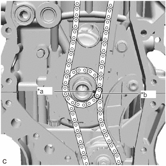
| *a | Timing Mark |
| *b | Mark Plate (Pink) |
Align the mark plate (pink) with timing mark and install the chain sub-assembly to the crankshaft timing sprocket.
Check that each timing mark is at TDC (compression).
| *a | Mark Plate (Orange) | *b | Mark Plate (Pink) |
| *c | Timing Mark | *d | Timing Mark (Rectangle) |
| *e | Mark (Circle) | - | - |
- HINT:
-
There are 3 marks on the camshaft timing sprocket. Make sure that the timing mark (rectangle) is at the top.
Remove the crankshaft pulley set bolt from the crankshaft.
13562
14.INSTALL NO. 2 CHAIN VIBRATION DAMPER
13559
15.INSTALL CHAIN TENSIONER SLIPPER
11302
16.INSTALL TIMING CHAIN COVER SUB-ASSEMBLY
11302A
17.INSTALL TIMING CHAIN COVER OIL SEAL
13540
18.INSTALL NO. 1 CHAIN TENSIONER ASSEMBLY
13471
19.INSTALL CRANKSHAFT PULLEY
11193
20.INSTALL SPARK PLUG TUBE GASKET
11213
21.INSTALL CYLINDER HEAD COVER GASKET
11201
22.INSTALL CYLINDER HEAD COVER SUB-ASSEMBLY
11101E
23.INSTALL CAMSHAFT POSITION SENSOR
19500
24.INSTALL IGNITION COIL ASSEMBLY
23250
25.INSTALL FUEL INJECTOR ASSEMBLY
23807V
26.INSTALL NO. 1 DELIVERY PIPE SPACER
23807
27.INSTALL FUEL DELIVERY PIPE SUB-ASSEMBLY
23818
28.INSTALL FUEL VAPOR FEED PIPE
17650G
29.INSTALL PURGE VALVE (PURGE VSV)
1628A
30.INSTALL WATER BY-PASS PIPE NO.6
11452
31.INSTALL ENGINE OIL LEVEL DIPSTICK GUIDE
15301
32.INSTALL ENGINE OIL LEVEL DIPSTICK
17111
33.INSTALL INTAKE MANIFOLD
17141
34.INSTALL EXHAUST MANIFOLD (TWC: Front Catalyst)
17167
35.INSTALL NO. 1 EXHAUST MANIFOLD HEAT INSULATOR
25620
36.TEMPORARILY INSTALL EGR VALVE ASSEMBLY WITH EGR COOLER
25610
37.TEMPORARILY INSTALL EGR PIPE ASSEMBLY
25620
38.INSTALL EGR VALVE ASSEMBLY WITH EGR COOLER
25610
39.INSTALL EGR PIPE ASSEMBLY
16331
40.INSTALL WATER OUTLET
41.INSTALL ENGINE HANGERS