THEFT DETERRENT / KEYLESS ENTRY ENTRY AND START SYSTEM(for Start Function) Immobiliser System does not Operate Properly
DESCRIPTION
The immobiliser function compares the ID code that is registered to the certification ECU (smart key ECU assembly) with the ID code of the transponder chip that is embedded in the electrical key transmitter sub-assembly.
WIRING DIAGRAM
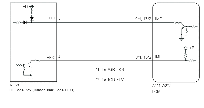
CAUTION / NOTICE / HINT
- NOTICE:
- ·
When using the GTS with the engine switch off, connect the GTS to the DLC3 and turn a courtesy light switch on and off at intervals of 1.5 seconds or less until communication between the GTS and the vehicle begins. Then select Model Code "KEY REGIST" under manual mode and enter the following menus: Body Electrical / Entry&Start. While using the GTS, periodically turn a courtesy light switch on and off at intervals of 1.5 seconds or less to maintain communication between the GTS and the vehicle.
·The entry and start system (for Start Function) uses the LIN communication system and CAN communication system. Inspect the communication function by following How to Proceed with Troubleshooting. Troubleshoot the entry and start system (for Start Function) after confirming that the communication systems are functioning properly.
·Before replacing the ID code box (immobiliser code ECU) or ECM, refer to the Service Bulletin.
·Make sure that no DTCs are output. If any DTCs are output, proceed to the Diagnostic Trouble Code Chart.
·After completing repairs, confirm that the problem does not recur.
·After repair, confirm that no DTCs are output by performing "DTC Output Confirmation Operation".
PROCEDURE
Connect the GTS to the DLC3.
Turn the engine switch on (IG).
Turn the GTS on.
Enter the following menus: Body Electrical or Powertrain / Entry&Start, Engine / Trouble Codes.
Check for DTCs.
- Body Electrical > Entry&Start > Trouble Codes
- 50001 125
- Powertrain > Engine > Trouble Codes
- 50001 372
- Result:
Result Proceed to DTCs are not output A DTCs are output B
A
B
Enter the following menus: Powertrain / Engine / Data List.
Read the Data List according to the display on the GTS.
- Powertrain > Engine > Data List
-
Tester Display Measurement Item Range Normal Condition Diagnostic Note Immobiliser Fuel Cut Status Status of immobiliser fuel cut OFF or ON OFF: Fuel cut off
ON: Fuel cut on-
- Powertrain > Engine > Data List
-
Tester Display Immobiliser Fuel Cut Status - 50003 372 65
- OK:
OFF is displayed after the engine is started.
- Result:
Proceed to OK (for 7GR-FKS) OK (for 1GD-FTV) NG
OK (for 7GR-FKS)
OK (for 1GD-FTV)
for 1GD-FTV (w/ DPF):
for 1GD-FTV (w/ EGR Cooler):
for 1GD-FTV (w/o EGR Cooler):
for 1GD-FTV (for Water Cooled Type Intercooler):
for 1GD-FTV (w/ Exhaust Gas Temperature Sensor for EGR):
NG
Check that the engine starts within 5 seconds of the engine switch being turned on (IG).
- OK:
Engine starts normally.
- Result:
Proceed to OK NG
OK
NG
Using an oscilloscope, check the waveform.
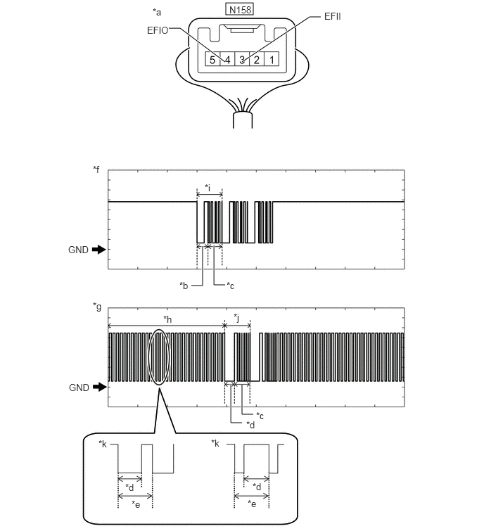
| *a | Component with harness connected
(ID Code Box (Immobiliser Code ECU)) |
*b | Approximately 160 ms. |
| *c | Approximately 270 ms. | *d | Approximately 40 ms. |
| *e | Approximately 60 ms. | *f | IMO Waveform |
| *g | IMI Waveform | *h | Waveform A |
| *i | Waveform B | *j | Waveform C |
| *k | Waveform A (detail) | - | - |
- NOTICE:
-
The waveform shown in the illustration is an example for reference only. Noise, chattering, etc. are not shown.
- Measurement Condition:
Tester Connection Condition Tool Setting Specified Condition N158-3 (EFII) - Body ground Within 3 seconds of engine start or within 3 seconds of engine switch turned on (IG) after cable disconnected and reconnected to battery 2 V/DIV., 500 ms./DIV. Pulse generation
(See waveform B)N158-4 (EFIO) - Body ground Within 3 seconds of engine start or within 3 seconds of engine switch turned on (IG) after cable disconnected and reconnected to battery 2 V/DIV., 500 ms./DIV. Pulse generation
(See waveform A and C)
- Result:
Result Proceed to Normal waveform A Waveform A is not output, or has abnormal wavelength or shape B Waveform B is not output, or has abnormal wavelength or shape C Waveform C is not output, or has abnormal wavelength or shape D
A
B
C
for 7GR-FKS:
for 1GD-FTV:
D
Register the ECU communication ID codes.
- HINT:
-
Refer to the Service Bulletin.
- Result:
Proceed to NEXT
NEXT
Check that the engine starts.
- OK:
Engine starts normally.
- Result:
Proceed to OK NG
OK
NG
Disconnect the N158 ID code box (immobiliser code ECU) connector.
for 7GR-FKS:
Disconnect the A1 ECM connector.
for 1GD-FTV:
Disconnect the A2 ECM connector.
Measure the resistance according to the value(s) in the table below.
- Standard Resistance:
for 7GR-FKS Tester Connection Condition Specified Condition N158-3 (EFII) - A1-9 (IMO) Always Below 1 Ω N158-4 (EFIO) - A1-8 (IMI) Always Below 1 Ω N158-3 (EFII) or A1-9 (IMO) - Other terminals and body ground Always 10 kΩ or higher N158-4 (EFIO) or A1-8 (IMI) - Other terminals and body ground Always 10 kΩ or higher
for 1GD-FTV Tester Connection Condition Specified Condition N158-3 (EFII) - A2-17 (IMO) Always Below 1 Ω N158-4 (EFIO) - A2-16 (IMI) Always Below 1 Ω N158-3 (EFII) or A2-17 (IMO) - Other terminals and body ground Always 10 kΩ or higher N158-4 (EFIO) or A2-16 (IMI) - Other terminals and body ground Always 10 kΩ or higher
- Result:
Proceed to OK NG
OK
NG
Replace the ID code box (immobiliser code ECU) with a new one.
- HINT:
-
Refer to the Service Bulletin.
- Result:
Proceed to NEXT
NEXT
Register the recognition codes to the ECUs.
- HINT:
-
Refer to the Service Bulletin.
- Result:
Proceed to NEXT
NEXT
Register the ECU communication ID codes.
- HINT:
-
Refer to the Service Bulletin.
- Result:
Proceed to NEXT
NEXT
Check that the engine starts.
- OK:
Engine starts normally.
- Result:
Proceed to OK NG (for 7GR-FKS) NG (for 1GD-FTV)
OK
NG (for 7GR-FKS)
NG (for 1GD-FTV)
for 1GD-FTV (w/ DPF):
for 1GD-FTV (w/ EGR Cooler):
for 1GD-FTV (w/o EGR Cooler):
for 1GD-FTV (for Water Cooled Type Intercooler):
for 1GD-FTV (w/ Exhaust Gas Temperature Sensor for EGR):