DOOR / HATCH BACK DOOR(for Double Swing Out Type) REASSEMBLY
PROCEDURE

 68987
1.INSTALL BACK DOOR STAY HOOK
68987
1.INSTALL BACK DOOR STAY HOOK

Install the back door stay hook with the 2 bolts.
- Torque:
- 5.0 N*m (51 kgf*cm, 44 in.*lbf)
- HINT:
-
Use the same procedure for the other side.
52166A
2.INSTALL REAR BUMPER UPPER COVER LH
52165A
3.INSTALL REAR BUMPER UPPER COVER RH
- HINT:
-
Use the same procedure described for the LH side.
4.INSTALL CENTER PILLAR OUTER PROTECTOR (for High Roof)
- HINT:
-
When installing the center pillar outer protector, heat the vehicle body and center pillar outer protector using a heat light.
| Item | Temperature |
|---|---|
| Vehicle Body | 20 to 30°C (68 to 86°F) |
| Center Pillar Outer Protector | 20 to 30°C (68 to 86°F) |
- CAUTION:
-
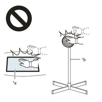 2.365,2 2.698,2 false 0.5,2.333 0.5,2.667 true 0.427,2.708 0.74,2.865 0.313,0.156 10 false *a 2.76,1.927 3.073,2.083 0.313,0.156 10 false *b
*a Heated Part *b Heat Light
- ·
Do not touch the heat light and heated parts.
·Touching the heat light may result in burns.
·Touching heated parts for a long time may result in burns.
- NOTICE:
-
Do not heat the vehicle body or center pillar outer protector excessively.
Clean the vehicle body surface.
Using a heat light, heat the vehicle body surface.
Wipe off any tape adhesive residue with cleaner.
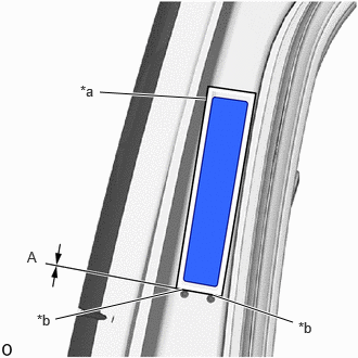
| *a | Release Paper |
| *b | Press Line |
Align the lower end of the release paper with the press line and install a new center pillar outer protector as shown in the illustration.
- Standard Value:
Area Dimensions A 0 mm (0 in.)
- HINT:
-
Use the same procedure for the RH and LH sides.
68896
5.INSTALL BACK DOOR LOWER HINGE NO. 1 FEMALE COVER LH
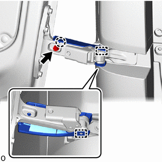
Attach the claw and guide.
Install the back door lower hinge No. 1 female cover LH with the screw.
68895
6.INSTALL BACK DOOR LOWER HINGE NO. 1 FEMALE COVER RH
- HINT:
-
Use the same procedure described for the LH side.
68856B
7.INSTALL BACK DOOR UPPER HINGE NO. 1 FEMALE COVER LH
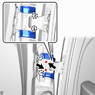
Attach the claw.
Install the back door upper hinge No. 1 female cover LH with the 2 screws.
68855B
8.INSTALL BACK DOOR UPPER HINGE NO. 1 FEMALE COVER RH
- HINT:
-
Use the same procedure described for the LH side.
67882C
9.INSTALL BACK DOOR NO. 2 WEATHERSTRIP (for Standard Roof)
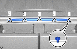
Attach the clips in the order shown in the illustration and install the back door No. 2 weatherstrip.
67882C
10.INSTALL BACK DOOR NO. 2 WEATHERSTRIP (for High Roof)
- HINT:
-
When installing the back door No. 2 weatherstrip, heat the vehicle body and back door No. 2 weatherstrip using a heat light.
| Item | Temperature |
|---|---|
| Vehicle Body | 40 to 60°C (104 to 140°F) |
| Back Door No. 2 Weatherstrip | 20 to 30°C (68 to 86°F) |
- NOTICE:
-
Do not heat the vehicle body or back door No. 2 weatherstrip excessively.
- CAUTION:
-
2.365,2 2.698,2 false 0.5,2.333 0.5,2.667 true 0.427,2.708 0.74,2.865 0.313,0.156 10 false *a 2.76,1.927 3.073,2.083 0.313,0.156 10 false *b
*a Heated Part *b Heat Light
- ·
Do not touch the heat light and heated parts.
·Touching the heat light may result in burns.
·Touching heated parts for a long time may result in burns.
Clean the vehicle body surface.
Using a heat light, heat the vehicle body surface.
Remove any remaining double-sided tape from the vehicle body.
Wipe off any tape adhesive residue with cleaner.

|
Double-sided Tape |
Install a new back door No. 2 weatherstrip.
Using a heat light, heat the vehicle body and back door No. 2 weatherstrip.
Remove the release paper from the back door No. 2 weatherstrip.
- HINT:
-
After removing the release paper, keep the exposed adhesive free from foreign matter.
Degrease the back door No. 2 weatherstrip installation surface using non-residue solvent.
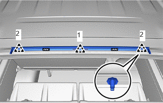
Attach the clip in the order shown in the illustration and install the back door No. 2 weatherstrip with double-sided tape.
- NOTICE:
-
Press the double-sided tape on the back door No. 2 weatherstrip firmly to apply it.
69430C
11.INSTALL BACK DOOR LOCK STRIKER ASSEMBLY
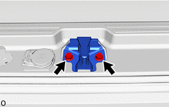
Install the back door lock striker assembly with the 2 bolts.
- Torque:
- 19 N*m (194 kgf*cm, 14 ft.*lbf)
69046
12.TEMPORARILY INSTALL BACK DOOR LOWER DOWN FEMALE STOPPER SUB-ASSEMBLY
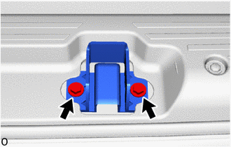
Temporarily install the back door lower down female stopper sub-assembly with the 2 bolts.
69462
13.INSTALL BACK DOOR SIDE MALE STOPPER LH

Install the back door side male stopper LH with the 2 bolts.
- Torque:
- 7.9 N*m (81 kgf*cm, 70 in.*lbf)
69047
14.TEMPORARILY INSTALL BACK DOOR UPPER LOCK STRIKER SUB-ASSEMBLY
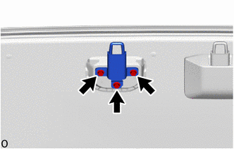
for Standard Roof:
Temporarily install the back door upper lock striker sub-assembly with the 3 bolts.
for High Roof:
Temporarily install the back door upper lock striker sub-assembly with the 3 bolts.
- HINT:
-
Use the same procedure for the other side.
15.INSTALL CENTER PILLAR OUTER PROTECTOR (for High Roof)
- HINT:
-
When installing the center pillar outer protector, heat the vehicle body and center pillar outer protector using a heat light.
| Item | Temperature |
|---|---|
| Vehicle Body | 20 to 30°C (68 to 86°F) |
| Center Pillar Outer Protector | 20 to 30°C (68 to 86°F) |
- CAUTION:
-
2.365,2 2.698,2 false 0.5,2.333 0.5,2.667 true 0.427,2.708 0.74,2.865 0.313,0.156 10 false *a 2.76,1.927 3.073,2.083 0.313,0.156 10 false *b
*a Heated Part *b Heat Light
- ·
Do not touch the heat light and heated parts.
·Touching the heat light may result in burns.
·Touching heated parts for a long time may result in burns.
- NOTICE:
-
Do not heat the vehicle body or center pillar outer protector excessively.
Clean the vehicle body surface.
Using a heat light, heat the vehicle body surface.
Wipe off any tape adhesive residue with cleaner.
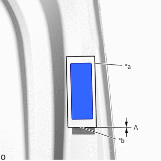
| *a | Release Paper |
| *b | Press Line |
Align the lower end of the release paper with the press line and install a new center pillar outer protector as shown in the illustration.
- Standard Value:
Area Dimensions A 0 mm (0 in.)
68957C
16.INSTALL BACK DOOR STAY HOLDER

Attach the claw and install the back door stay holder.
68955
17.INSTALL BACK DOOR STAY BRACKET
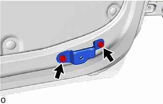
Install the back door stay bracket with the 2 bolts.
- Torque:
- 5.0 N*m (51 kgf*cm, 44 in.*lbf)
68933
18.INSTALL BACK DOOR NO. 2 STAY
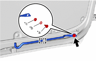
| *a | Bolt |
| *b | Wave Washer |
| *c | Bush |
Attach the clamp and using a socket wrench, install the back door No. 2 stay, wave washer and bush with the bolt.
- Torque:
- 5.0 N*m (51 kgf*cm, 44 in.*lbf)
67772S
19.INSTALL DOOR TRIM RETAINER CAP
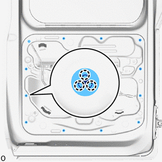
Attach the claw and install the 12 door trim retainer caps.
69359
20.INSTALL BACK DOOR LOCK CUSHION
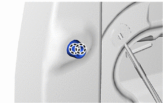
Attach the claw and install the back door lock cushion.
67837L
21.INSTALL DOOR DUST PROOF SEAL
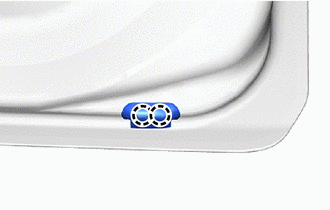
Attach the claw and install the door dust proof seal.
67884A
22.INSTALL BACK DOOR CENTER WEATHERSTRIP
Remove the release paper from the back door center weatherstrip.
- HINT:
-
After removing the release paper, keep the exposed adhesive free from foreign matter.
Attach the clip in the order shown in the illustration and install the back door center weatherstrip with butyl tape.
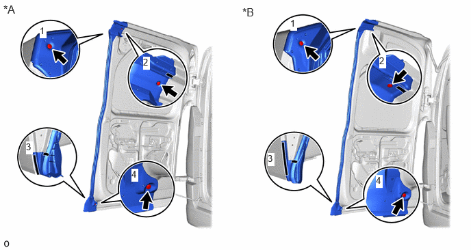
| *A | for Standard Roof | *B | for High Roof |

|
Butyl Tape | - | - |
- NOTICE:
-
When installing, make sure that non-drying sealer does not adhere to the body and back door.
69430C
23.INSTALL BACK DOOR LOCK STRIKER ASSEMBLY
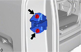
Install the back door lock striker assembly with the 2 bolts.
- Torque:
- 19 N*m (194 kgf*cm, 14 ft.*lbf)
69042
24.INSTALL BACK DOOR LOWER STOPPER SUB-ASSEMBLY
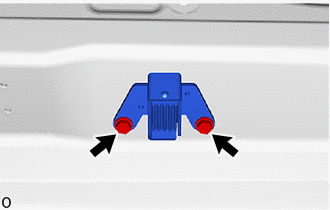
Install the back door lower stopper sub-assembly with the 2 bolts.
- Torque:
- 7.9 N*m (81 kgf*cm, 70 in.*lbf)
69380C
25.INSTALL BACK DOOR LOWER LOCK ASSEMBLY
Apply MP grease to the sliding parts of the back door lower lock assembly.
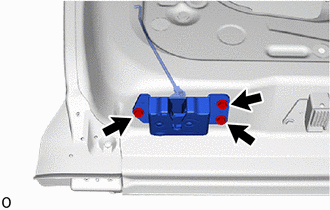
Install the back door lower lock assembly with the 3 bolts.
- Torque:
- 12.5 N*m (127 kgf*cm, 9 ft.*lbf)
69461A
26.INSTALL BACK DOOR SIDE MALE STOPPER
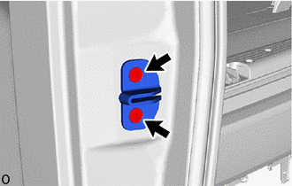
Using a T30 "TORX" socket wrench, install the back door side male stopper with the 2 "TORX" screws.
- Torque:
- 7.0 N*m (71 kgf*cm, 62 in.*lbf)
64680
27.INSTALL BACK DOOR LOCK CONTROL CABLE ASSEMBLY
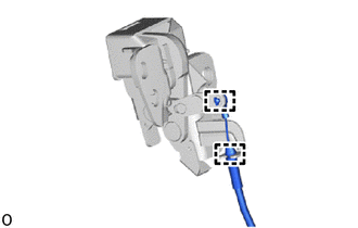
Attach the clamp and install the back door lock control cable assembly.
69360G
28.TEMPORARILY INSTALL BACK DOOR LOCK ASSEMBLY LH
When reusing the bolt:
Clean the threads of the bolt with non-residue solvent.
Apply adhesive to the threads of the bolt.
- Adhesive:
Toyota Genuine Adhesive 1324, Three Bond 1324 or equivalent.
Apply MP grease to the sliding parts of the back door lock assembly LH.
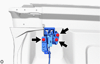
Temporarily install the back door lock assembly LH with the 3 bolts.
69660
29.INSTALL BACK DOOR LOCK REMOTE CONTROL ASSEMBLY LH
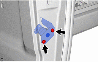
Install the back door lock remote control assembly LH with the 2 screws.
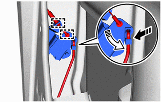

|
Install in this Direction (1) |

|
Install in this Direction (2) |
Attach the snap and connect the back door lower lock assembly as shown in the illustration.
Attach the clamp and connect the back door lock control cable assembly.
69291
30.INSTALL BACK DOOR INSIDE HANDLE ASSEMBLY
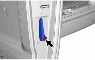
Install the back door inside handle assembly with the screw.
69360G
31.INSTALL BACK DOOR LOCK ASSEMBLY LH
Fully close the back door panel LH.
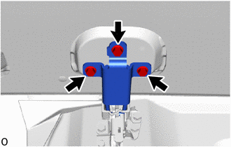
Tighten the 3 bolts and install the back door upper lock striker sub-assembly.
- Torque:
- 19 N*m (194 kgf*cm, 14 ft.*lbf)
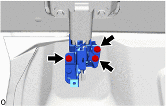
Tighten the 3 bolts and install the back door lock assembly LH.
- Torque:
- 18.2 N*m (186 kgf*cm, 13 ft.*lbf)
Open the back door panel LH.
69321
32.INSTALL BACK DOOR LOCK COVER (for High Roof)
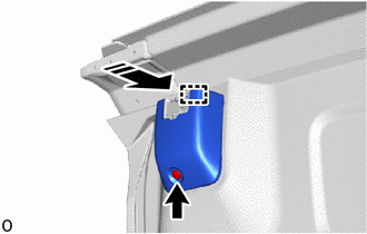
|
|
Install in this Direction |
Attach the guide and install the back door lock cover as shown in the illustration.
Install the clip.
85035R
33.INSTALL REAR WASHER NOZZLE SUB-ASSEMBLY (w/ Rear Wiper)
85143R
34.INSTALL REAR WIPER MOTOR GROMMET (w/ Rear Wiper)
85110R
35.INSTALL REAR WIPER MOTOR ASSEMBLY (w/ Rear Wiper)
36.INSTALL REAR WIPER ARM AND BLADE ASSEMBLY LH (w/ Rear Wiper)
867C0
37.INSTALL INNER MIRROR CAMERA ASSEMBLY (w/ Digital Inner Mirror)
76839A
38.INSTALL BACK DOOR GARNISH COVER (w/ Digital Inner Mirror)
76839C
39.INSTALL BACK DOOR GARNISH COVER (w/o Rear View Monitor System)
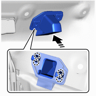
|
|
Install in this Direction |
Attach the claw and install the back door garnish cover as shown in the illustration.
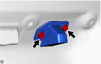
Install the 2 screws.
86790
40.INSTALL TELEVISION CAMERA ASSEMBLY (w/ Rear View Monitor System)
81204A
41.INSTALL LICENSE PLATE LIGHT ASSEMBLY
76801
42.INSTALL BACK DOOR OUTSIDE GARNISH SUB-ASSEMBLY
87950
43.INSTALL OUTER UNDER REAR VIEW MIRROR ASSEMBLY (w/ Outer Under Rear View Mirror)
67760A
44.INSTALL BACK DOOR UPPER TRIM BOARD ASSEMBLY
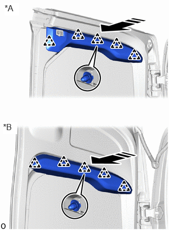
| *A | for Standard Roof |
| *B | for High Roof |
|
|
Install in this Direction |
Attach the clip and install the back door upper trim board assembly as shown in the illustration.
67290
45.INSTALL BACK DOOR DAMPER ASSEMBLY (for Standard Roof)
Attach the guide and install the back door damper assembly.
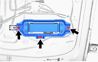
Install the 3 bolts.
- Torque:
- 12.5 N*m (127 kgf*cm, 9 ft.*lbf)
67751
46.INSTALL BACK DOOR TRIM BOARD
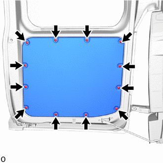
Install the back door trim board with the 12 clips.
47.INSTALL CENTER PILLAR OUTER PROTECTOR (for High Roof)
- HINT:
-
When installing the center pillar outer protector, heat the vehicle body and center pillar outer protector using a heat light.
| Item | Temperature |
|---|---|
| Vehicle Body | 20 to 30°C (68 to 86°F) |
| Center Pillar Outer Protector | 20 to 30°C (68 to 86°F) |
- CAUTION:
-
2.365,2 2.698,2 false 0.5,2.333 0.5,2.667 true 0.427,2.708 0.74,2.865 0.313,0.156 10 false *a 2.76,1.927 3.073,2.083 0.313,0.156 10 false *b
*a Heated Part *b Heat Light
- ·
Do not touch the heat light and heated parts.
·Touching the heat light may result in burns.
·Touching heated parts for a long time may result in burns.
- NOTICE:
-
Do not heat the vehicle body or center pillar outer protector excessively.
Clean the vehicle body surface.
Using a heat light, heat the vehicle body surface.
Wipe off any tape adhesive residue with cleaner.
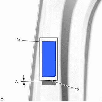
| *a | Release Paper |
| *b | Press Line |
Align the lower end of the release paper with the press line and install a new center pillar outer protector as shown in the illustration.
- Standard Value:
Area Dimensions A 0 mm (0 in.)
68957C
48.INSTALL BACK DOOR STAY HOLDER
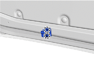
Attach the claw and install the back door stay holder.
68955
49.INSTALL BACK DOOR STAY BRACKET
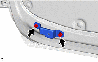
Install the back door stay bracket with the 2 bolts.
- Torque:
- 5.0 N*m (51 kgf*cm, 44 in.*lbf)
68931
50.INSTALL BACK DOOR NO. 1 STAY
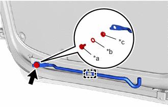
| *a | Bolt |
| *b | Wave Washer |
| *c | Bush |
Attach the clamp and using a socket wrench, install the back door No. 1 stay, wave washer and bush with the bolt.
- Torque:
- 5.0 N*m (51 kgf*cm, 44 in.*lbf)
67772S
51.INSTALL DOOR TRIM RETAINER CAP
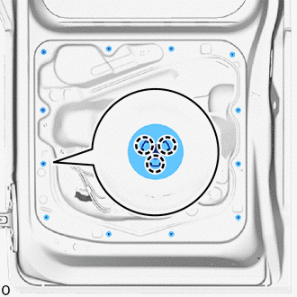
Attach the claw and install the 12 door trim retainer caps.
52.INSTALL SCREW GROMMET
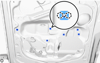
Attach the claw and install the 6 screw grommets.
67837L
53.INSTALL DOOR DUST PROOF SEAL
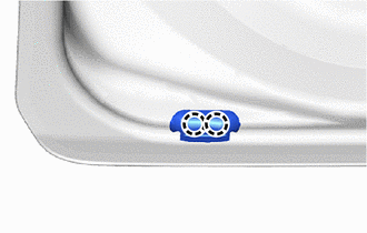
Attach the claw and install the door dust proof seal.
69462
54.INSTALL BACK DOOR SIDE MALE STOPPER LH
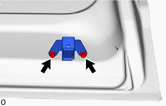
Install the back door side male stopper LH with the 2 bolts.
- Torque:
- 7.9 N*m (81 kgf*cm, 70 in.*lbf)
69046
55.INSTALL BACK DOOR LOWER DOWN FEMALE STOPPER SUB-ASSEMBLY
Fully close the back door panel RH.
Open the back door panel RH.
Tighten the 2 bolts and install the back door lower down female stopper sub-assembly.
- Torque:
- 7.9 N*m (81 kgf*cm, 70 in.*lbf)
69403A
56.INSTALL BACK DOOR SIDE FEMALE STOPPER SUB-ASSEMBLY RH
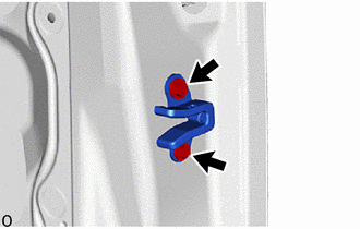
Temporarily install the back door side female stopper sub-assembly RH with the 2 bolts.
Fully close the back door panel LH and RH.
Open the back door panel LH and RH.
Tighten the 2 bolts and install the back door side female stopper sub-assembly RH.
- Torque:
- 5.6 N*m (57 kgf*cm, 50 in.*lbf)
69690
57.INSTALL BACK DOOR REMOTE CONTROL ASSEMBLY
Apply MP grease to the sliding parts of the back door remote control assembly.

| *a | Guide |
| *b | Wire Harness Clamp |

|
Screw |

|
Connector |
Attach the guide and install the back door remote control assembly.
Install the 3 screws.
Attach the wire harness clamp.
Connect the connector.
69356A
58.INSTALL BACK DOOR UPPER ROD

|
|
Install in this Direction (1) |
|
|
Install in this Direction (2) |
Attach the snap and install the back door upper rod as shown in the illustration.
69650
59.INSTALL BACK DOOR LOCK REMOTE CONTROL ASSEMBLY RH
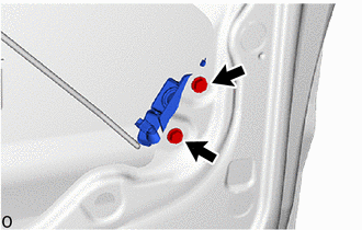
Install the back door lock remote control assembly RH with the 2 bolts.
- Torque:
- 5.0 N*m (51 kgf*cm, 44 in.*lbf)
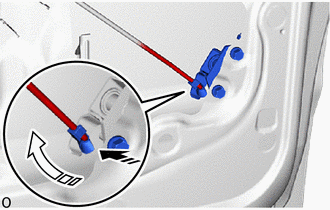
|
|
Install in this Direction (1) |
|
|
Install in this Direction (2) |
Attach the snap and connect the back door remote control assembly as shown in the illustration.
69351
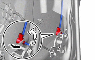
60.INSTALL BACK DOOR UPPER LOCK CONTROL ROD
|
|
Install in this Direction (1) |
|
|
Install in this Direction (2) |
Attach the snap and install the back door upper lock control rod as shown in the illustration.
69201B
61.INSTALL BACK DOOR OUTSIDE HANDLE FRAME SUB-ASSEMBLY
Apply MP grease to the sliding parts of the back door outside handle frame sub-assembly.
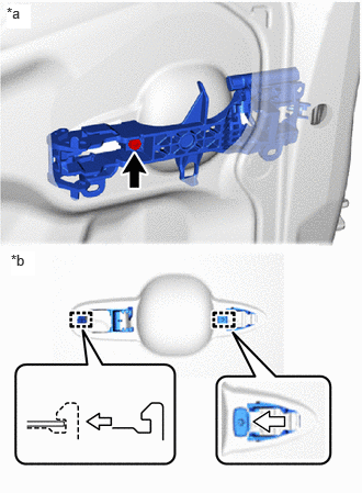
| *a | Inside |
| *b | Outside |
Attach the guide and install the back door outside handle frame sub-assembly as shown in the illustration.
Using a T30 "TORX" socket wrench, install the back door outside handle frame sub-assembly with the "TORX" screw.
- Torque:
- 4.0 N*m (41 kgf*cm, 35 in.*lbf)
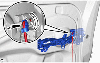
|
|
Install in this Direction (1) |
|
|
Install in this Direction (2) |
Attach the snap and connect the back door upper lock control rod as shown in the illustration.
69241F
62.INSTALL DOOR OUTSIDE HANDLE PAD
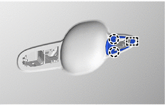
Attach the claw and guide to install the door outside handle pad.
69242M
63.INSTALL BACK DOOR REAR OUTSIDE HANDLE PAD
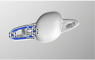
Attach the guide and install the back door rear outside handle pad.
69055B
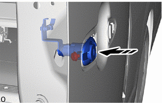
64.INSTALL BACK DOOR LOCK CYLINDER ASSEMBLY
|
|
Install in this Direction |
Insert the back door lock cylinder assembly as shown in the illustration.
Using a T30 "TORX" socket wrench, install the back door lock cylinder assembly with the "TORX" screw.
- Torque:
- 4.0 N*m (41 kgf*cm, 35 in.*lbf)
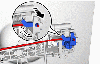
|
|
Install in this Direction (1) |
|
|
Install in this Direction (2) |
Attach the snap and connect the back door upper rod as shown in the illustration.
69211C
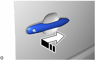
65.INSTALL BACK DOOR OUTSIDE HANDLE
|
|
Install in this Direction |
Install the back door outside handle in the direction of the arrow shown in the illustration.
| *1 | Holder |
|
|
Install in this Direction |
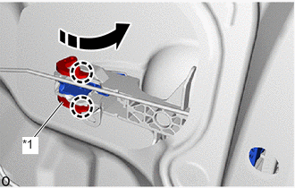
Lower the lever in the direction indicated by the arrow shown in the illustration and attach the claw.
66.INSTALL HOLE PLUG
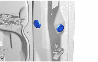
Install the 2 hole plugs.
69290F
67.INSTALL BACK DOOR INSIDE HANDLE ASSEMBLY (w/ Handle)
Apply MP grease to the sliding parts of the back door inside handle assembly.
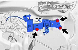
Attach the guide and install the back door inside handle assembly.
Install the 3 screws.
|
|
Install in this Direction (1) |
|
|
Install in this Direction (2) |
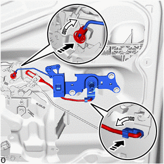
Attach the 2 snaps and connect the back door inside handle assembly and back door remote control assembly as shown in the illustration.
69350
68.INSTALL BACK DOOR LOCK ASSEMBLY
Apply MP grease to the sliding parts of the back door lock assembly.
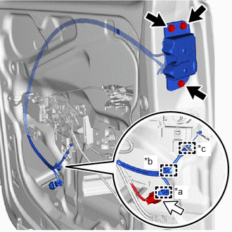
| *a | Wire Harness Clamp |
| *b | Cable Clamp |
| *c | Clamp |
|
|
Bolt |
|
|
Connector |
Install the back door lock assembly with the 3 bolts.
- Torque:
- 12.5 N*m (127 kgf*cm, 9 ft.*lbf)
Attach the clamp and connect the back door lock assembly.
Attach the wire harness clamp and cable clamp.
Connect the connector.
69.INSTALL CLAMP (for High Roof)
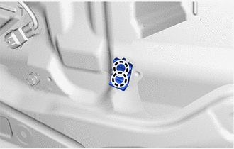
Attach the claw and install the clamp.
64680
70.INSTALL BACK DOOR LOCK CONTROL CABLE ASSEMBLY (for High Roof)
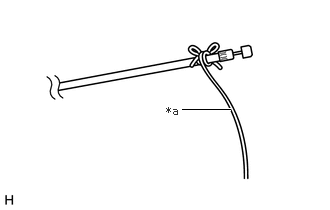
| *a | String |
Tie a string to the end of the back door lock control cable assembly.
Pull the string from the top until the back door lock control cable assembly passes through.
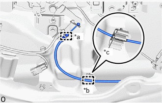
| *a | Clamp |
| *b | Cable Clamp |
| *c | Tape |
Attach the cable clamp as shown in the illustration.
Attach the clamp and install the back door lock control cable assembly.
69350T
71.INSTALL BACK DOOR LOCK ASSEMBLY RH (for High Roof)
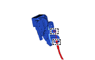
Attach the clamp and connect the back door lock assembly RH.
When reusing the bolt:
Clean the threads of the bolt with non-residue solvent.
Apply adhesive to the threads of the bolt.
- Adhesive:
Toyota Genuine Adhesive 1324, Three Bond 1324 or equivalent.
Apply MP grease to the sliding parts of the back door lock assembly RH.
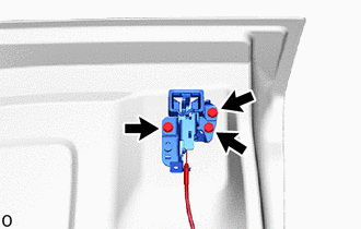
Temporarily install the back door lock assembly RH with the 3 bolts.
Fully close the back door RH.
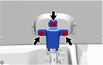
Tighten the 3 bolts and install the back door upper lock striker sub-assembly.
- Torque:
- 19 N*m (194 kgf*cm, 14 ft.*lbf)
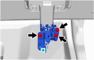
Tighten the 3 bolts and install the back door lock assembly RH.
- Torque:
- 18.2 N*m (186 kgf*cm, 13 ft.*lbf)
Open the back door panel RH.
69321
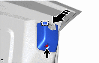
72.INSTALL BACK DOOR LOCK COVER (for High Roof)
|
|
Install in this Direction |
Attach the guide and install the back door lock cover as shown in the illustration.
Install the clip.
69455A
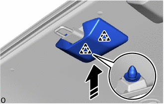
73.INSTALL BACK DOOR UPPER LOCK STRIKER COVER
|
|
Install in this Direction |
for Standard Roof:
Attach the clip and install the back door upper lock striker cover as shown in the illustration.
for High Roof:
Attach the clip and install the back door upper lock striker cover as shown in the illustration.
- HINT:
-
Use the same procedure for the RH and LH sides.
81570
74.INSTALL CENTER STOP LIGHT ASSEMBLY
85143R
75.INSTALL REAR WIPER MOTOR GROMMET (w/ Rear Wiper)
85110R
76.INSTALL REAR WIPER MOTOR ASSEMBLY (w/ Rear Wiper)
77.INSTALL REAR WIPER ARM AND BLADE ASSEMBLY RH (w/ Rear Wiper)
- HINT:
-
Use the same procedure described for the LH side.
67760A
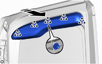
78.INSTALL BACK DOOR UPPER TRIM BOARD ASSEMBLY
|
|
Install in this Direction |
Attach the clip and install the back door upper trim board assembly.
67847A
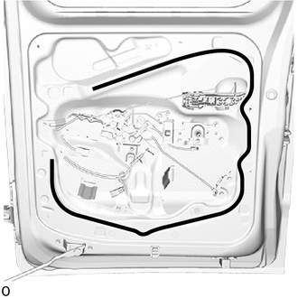
79.INSTALL BACK DOOR SERVICE HOLE COVER
|
|
Butyl Tape |
Apply new butyl tape to the back door panel as shown in the illustration.
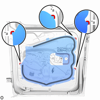
| *a | Reference Point |
|
|
Butyl Tape |
Install a new back door service hole cover according to the reference points on the back door panel.
67751
80.INSTALL BACK DOOR TRIM BOARD
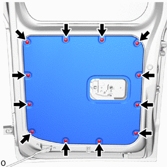
Install the back door trim board with the 12 clips.
69783B
81.INSTALL BACK DOOR INSIDE HANDLE BEZEL (w/ Handle)
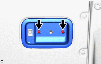
Install the back door inside handle bezel with the 2 screws.
69291
82.INSTALL BACK DOOR INSIDE HANDLE ASSEMBLY (w/ Handle)
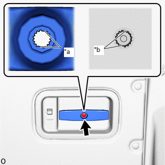
| *a | Large Protrusion |
| *b | Large Cutout |
Align the 2 large protrusions of the back door inside handle assembly with the 2 large cutouts of the back door remote control assembly and using a socket wrench, install the back door inside handle assembly with the screw as shown in the illustration.
- Torque:
- 7.0 N*m (71 kgf*cm, 62 in.*lbf)
69298
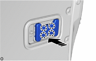
83.INSTALL BACK DOOR INSIDE HANDLE COVER (w/ Handle, Cover)
|
|
Install in this Direction |
Attach the claw and install the back door inside handle cover as shown in the illustration.
84.ADJUST TELEVISION CAMERA ASSEMBLY (w/ Rear View Monitor System)