STEERING GEAR / LINKAGE STEERING GEAR(for LHD) INSTALLATION
PROCEDURE

 1.ADJUST TIE ROD END SUB-ASSEMBLY

Adjust the tie rod end sub-assembly LH and RH so that distance A is within the specified ranges.
- Standard Length (A):
5.0 mm (0.1969 in.) or less
- CAUTION:
-
Make sure to tighten the nut in the alignment adjustment procedure.
- NOTICE:
-
Make sure that the boots are not twisted.
- HINT:
- ·
The values listed above are reference values.
·The toe-in is adjusted in another step.
45047
2.TEMPORARILY INSTALL TIE ROD END SUB-ASSEMBLY LH
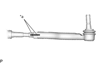
| *a | Matchmark |
Temporarily install the lock nut and tie rod assembly LH to the rack and pinion power steering gear assembly until the matchmarks are aligned.
- HINT:
-
After adjusting the toe-in, tighten the lock nut.
45046
3.TEMPORARILY INSTALL TIE ROD END SUB-ASSEMBLY RH
- HINT:
-
Perform the same procedure as for the LH side.
44250
4.INSTALL RACK AND PINION POWER STEERING GEAR ASSEMBLY
Install the power steering link assembly with the 2 bolts.
- Torque:
- 150 N*m (1530 kgf*cm, 111 ft.*lbf)
for 1GD-FTV:
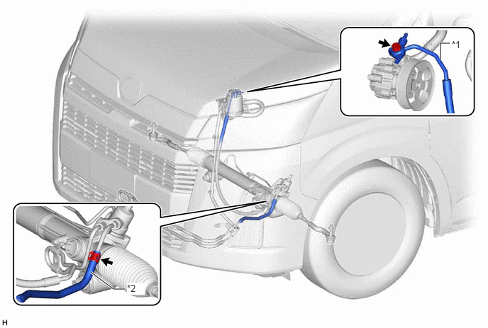
| *1 | Pressure Feed Tube | *2 | Return Hose |
Slide the clip and install the return hose.
Install a new gasket.
Install the union bolt and pressure feed tube.
- Torque:
- 50 N*m (510 kgf*cm, 37 ft.*lbf)
for 7GR-FKS:
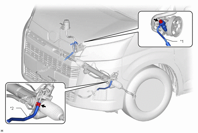
| *1 | Pressure Feed Tube | *2 | Return Hose |
Slide the clip and install the return hose.
Install a new gasket.
Install the union bolt and pressure feed tube.
- Torque:
- 50 N*m (510 kgf*cm, 37 ft.*lbf)
5.CONNECT INTERMEDIATE SHAFT ASSEMBLY
Align the matchmarks on the intermediate shaft assembly and power steering link assembly.
Install the bolt.
- Torque:
- 35 N*m (357 kgf*cm, 26 ft.*lbf)
45047
6.CONNECT TIE ROD END SUB-ASSEMBLY LH
Connect the tie rod end sub-assembly LH to the front axle hub assembly with nut.
- Torque:
- 100 N*m (1020 kgf*cm, 74 ft.*lbf)
Install a new cotter pin.
- NOTICE:
-
If the holes for the cotter pin are not aligned, tighten the nut an additional 60°.
45046
7.CONNECT TIE ROD END SUB-ASSEMBLY RH
- HINT:
-
Use the same procedure described for the LH side.
51108C
8.INSTALL REAR SIDE RAIL REINFORCEMENT SUB-ASSEMBLY
Install the 2 rear side rail reinforcement sub-assembly with the 8 bolts.
- Torque:
- 35 N*m (357 kgf*cm, 26 ft.*lbf)
51405A
9.INSTALL NO. 1 ENGINE UNDER COVER SUB-ASSEMBLY
52618
10.INSTALL LOWER FRONT BUMPER ABSORBER
51406A
11.INSTALL NO. 2 ENGINE UNDER COVER SUB-ASSEMBLY (w/ No. 2 Engine Under Cover Sub-assembly)
12.INSTALL FRONT WHEELS
13.ADD POWER STEERING FLUID
14.ADJUST POWER STEERING FLUID
15.CHECK FOR POWER STEERING FLUID LEAK
45047
17.FULLY TIGHTEN TIE ROD END SUB-ASSEMBLY LH
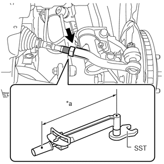
| *a | Torque Wrench Fulcrum Length |
Using SST, tighten the tie rod end sub-assembly lock nuts.
- SST
- 09922-10240
- Torque:
- Specified Tightening Torque : 62 N*m (632 kgf*cm, 46 ft.*lbf)
- NOTICE:
-
Make sure that the boots are not twisted.
- HINT:
- ·
Calculate the torque wrench reading when changing the fulcrum length of the torque wrench.
·When using SST (fulcrum length of 40 mm (1.575 in.)) + torque wrench (fulcrum length of 380 mm (14.961 in.)): 56.1 N*m (572 kgf*cm, 41 ft.*lbf)
45046
18.FULLY TIGHTEN TIE ROD END SUB-ASSEMBLY RH
- HINT:
-
Perform the same procedure as for the LH side.