TELEMATICS TELEMATICS TRANSCEIVER(for RHD) INSTALLATION
CAUTION / NOTICE / HINT
- HINT:
-
A bolt without a torque specification is shown in the standard bolt chart.
PROCEDURE

 86741A
1.INSTALL TELEMATICS TRANSCEIVER
86741A
1.INSTALL TELEMATICS TRANSCEIVER
86719B
2.INSTALL NO. 2 TELEPHONE BRACKET
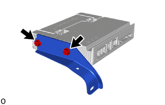
Install the No. 2 telephone bracket with the 2 screw.
86719A
3.INSTALL NO. 1 TELEPHONE BRACKET
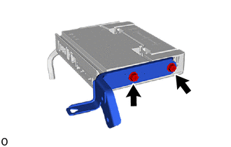
Install the No. 1 telephone bracket with the 2 screw.
4.INSTALL TELEMATICS TRANSCEIVER WITH BRACKET
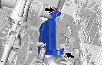
Install the telematics tansceiver with bracket with the 2 nuts.
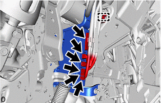
Attach the wire harness clamp.
Connect the 6 connectors.
73900
5.INSTALL LOWER NO. 1 INSTRUMENT PANEL AIRBAG ASSEMBLY
55433B
6.INSTALL LOWER NO. 2 INSTRUMENT PANEL FINISH PANE
55044C
7.INSTALL INSTRUMENT PANEL FINISH PANEL SUB-ASSEMBLY
55432D
8.INSTALL LOWER NO. 1 INSTRUMENT PANEL FINISH PANEL
77306
9.INSTALL FUEL LID LOCK OPEN LEVER SUB-ASSEMBLY
53601
10.INSTALL HOOD LOCK CONTROL LEVER SUB-ASSEMBLY
55641
11.INSTALL NO. 1 INSTRUMENT PANEL UNDER COVER
55317A
12.INSTALL INSTRUMENT SIDE PANEL RH
55011A
13.INSTALL NO. 1 INSTRUMENT PANEL GARNISH SUB-ASSEMBLY
55631A
14.INSTALL NO. 1 INSTRUMENT PANEL UNDER TRAY STOPPER
62111C
15.INSTALL COWL SIDE TRIM BOARD RH
67913B
16.INSTALL FRONT DOOR SCUFF PLATE RH
- HINT:
-
Use the same procedure described for the LH side.
67911B
17.INSTALL FRONT DOOR OUTSIDE SCUFF PLATE RH
- HINT:
-
Use the same procedure described for the LH side.
18.CONNECT CABLE TO NEGATIVE BATTERY TERMINAL
19. INITIALIZATION AFTER RECONNECTING BATTERY TERMINAL
- HINT:
-
When disconnecting and reconnecting the battery, there is an automatic learning function that completes learning when the respective system is used.
20. PERFORM DIAGNOSTIC SYSTEM CHECK
21.CHECK SRS WARNING LIGHT