AC60E AUTOMATIC TRANSMISSION / TRANSAXLE OIL COOLER(for 7GR-FKS) INSTALLATION
PROCEDURE

 32921
1.INSTALL NO. 1 OIL COOLER INLET TUBE AND NO. 1 OIL COOLER OUTLET TUBE
32921
1.INSTALL NO. 1 OIL COOLER INLET TUBE AND NO. 1 OIL COOLER OUTLET TUBE
Install the No. 2 oil cooler tube clamp and 2 transmission oil cooler tube clamp sub-assemblies to the automatic transmission assembly and engine assembly with the 3 bolts (A).
- Torque:
- 13.5 N*m (138 kgf*cm, 10 ft.*lbf)
- NOTICE:
-
When installing the No. 1 oil cooler inlet tube and No. 1 oil cooler outlet tube, support the tube by hand and be careful to prevent the tube from being deformed.
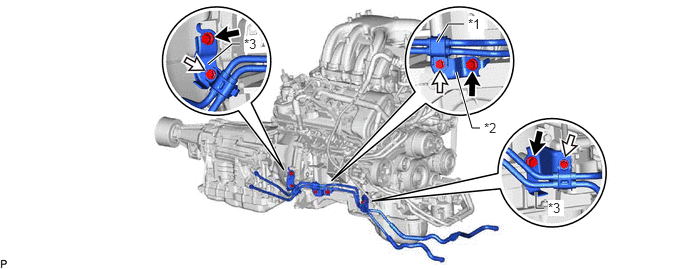
| *1 | No. 1 Automatic Transmission Oil Cooler Tube Clamp | *2 | No. 2 Oil Cooler Tube Clamp |
| *3 | Transmission Oil Cooler Tube Clamp Sub-assembly | - | - |

|
Bolt A | 
|
Bolt B |
Connect the ends of the No. 1 oil cooler inlet tube and No. 1 oil cooler outlet tube to the automatic transmission assembly by hand.
Close the No. 1 automatic transmission oil cooler tube clamp and 2 transmission oil cooler tube clamp sub-assemblies and install the 3 bolts (B).
- Torque:
- 5.2 N*m (53 kgf*cm, 46 in.*lbf)
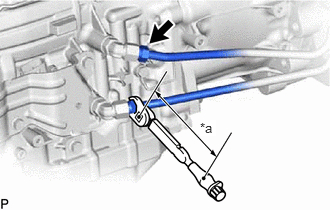
| *a | Torque Wrench Fulcrum Length |
Using a 17 mm union nut wrench, tighten the No. 1 oil cooler inlet tube and No. 1 oil cooler outlet tube.
- Torque:
- Specified tightening torque : 34.3 N*m (350 kgf*cm, 25 ft.*lbf)
- HINT:
- ·
Calculate the torque wrench reading when changing the fulcrum length of the torque wrench.
(Click hereGeneral>INTRODUCTION>REPAIR INSTRUCTION>PRECAUTION201902,999999,_V1,_078841,_0382392,RM100000001GTX7,)
·When using a union nut wrench (fulcrum length of 30 mm (1.181 in.)) + torque wrench (fulcrum length of 180 mm (7.087 in.)): 29.4 N*m (300 kgf*cm, 22 ft.*lbf)
32941
2.INSTALL NO. 1 OIL COOLER INLET HOSE AND NO. 1 OIL COOLER OUTLET HOSE
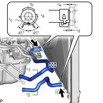
| *1 | No. 1 Oil Cooler Inlet Hose |
| *2 | No. 1 Oil Cooler Outlet Hose |
| *a | Right Side of Vehicle |
| *b | Upper Side of Vehicle |
| *c | Paint Mark |
| *d | 2 to 5 mm (0.0787 to 0.197 in.) |
| *e | 0 to 3 mm (0 to 0.118 in.) |
Install the No. 1 oil cooler inlet hose and No. 1 oil cooler outlet hose to the radiator assembly, and slide the 2 clips to secure the hose.
- NOTICE:
- ·
Make sure to slide the No. 1 oil cooler inlet hose and No. 1 oil cooler outlet hose until each contacts the hose stopper of the radiator assembly.
·Make sure that the claws of each clip are within the location shown in the illustration.
Connect the hose clamp to the fan shroud.

| *a | Right Side of Vehicle |
| *b | Upper Side of Vehicle |
| *c | Paint Mark |
| *d | 2 to 5 mm (0.0787 to 0.197 in.) |
| *e | 0 to 3 mm (0 to 0.118 in.) |
Connect the No. 1 oil cooler inlet hose and No. 1 oil cooler outlet hose to the No. 1 oil cooler inlet tube and No. 1 oil cooler outlet tube, and slide the 2 clips to secure the hose.
- NOTICE:
- ·
Make sure to slide the No. 1 oil cooler inlet hose and No. 1 oil cooler outlet hose until each contacts the hose stopper of the No. 1 oil cooler inlet tube and No. 1 oil cooler outlet tube.
·Make sure to align the paint mark of the No. 1 oil cooler inlet hose and No. 1 oil cooler outlet hose with the paint mark of the No. 1 oil cooler inlet tube and No. 1 oil cooler outlet tube.
·Make sure that the claws of each clip are within the location shown in the illustration.
17140
3.INSTALL EXHAUST MANIFOLD ASSEMBLY RH
4.ADJUST AUTOMATIC TRANSMISSION FLUID LEVEL