7GR-FKS INTAKE / EXHAUST EXHAUST MANIFOLD INSTALLATION
PROCEDURE

 17168
1.INSTALL NO. 2 EXHAUST MANIFOLD HEAT INSULATOR (w/o Secondary Air Injection System)
17168
1.INSTALL NO. 2 EXHAUST MANIFOLD HEAT INSULATOR (w/o Secondary Air Injection System)
Install the No. 2 exhaust manifold heat insulator to the exhaust manifold assembly LH with the 2 bolts.
- Torque:
- 13 N*m (133 kgf*cm, 10 ft.*lbf)
89467B
2.INSTALL AIR FUEL RATIO SENSOR (for Bank 2 Sensor 1)
17150
3.INSTALL EXHAUST MANIFOLD ASSEMBLY LH
Install a new gasket to the cylinder head LH.
- NOTICE:
-
Be careful of the installation direction.
w/o Secondary Air Injection System:
Temporarily install the exhaust manifold assembly LH with the 4 nuts.

Tighten the 4 nuts in the sequence shown in the illustration.
- Torque:
- 26 N*m (265 kgf*cm, 19 ft.*lbf)
Connect the air fuel ratio sensor connector and attach the wire harness clamp.
w/ Secondary Air Injection System:
Temporarily install the exhaust manifold assembly LH with the 6 nuts.
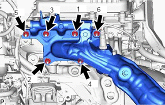
Tighten the 6 nuts in the sequence shown in the illustration.
- Torque:
- 26 N*m (265 kgf*cm, 19 ft.*lbf)
Connect the air fuel ratio sensor connector and attach the wire harness clamp.
17362
4.INSTALL NO. 2 AIR TUBE (w/ Secondary Air Injection System)

|
Bolt |

|
Nut |
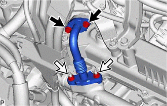
Install 2 new gaskets and the No. 2 air tube to the exhaust manifold assembly LH and No. 2 emission control valve set with the 2 bolts and 2 nuts.
- Torque:
- 20 N*m (204 kgf*cm, 15 ft.*lbf)
- NOTICE:
-
Do not reuse the gasket.
17119
5.INSTALL NO. 2 MANIFOLD STAY
Temporarily install the No. 2 manifold stay to the transmission assembly and exhaust manifold assembly LH with the 3 bolts.
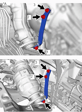
| *A | w/ Secondary Air Injection System |
| *B | w/o Secondary Air Injection System |
Tighten the 3 bolts in the sequence shown in the illustration.
- Torque:
- 40 N*m (408 kgf*cm, 30 ft.*lbf)
89467B
6.INSTALL AIR FUEL RATIO SENSOR (for Bank 1 Sensor 1)
17140
7.INSTALL EXHAUST MANIFOLD ASSEMBLY RH
Install a new gasket to the cylinder head assembly RH.
- NOTICE:
-
Be careful of the installation direction.
w/ Secondary Air Injection System:
Temporarily install the exhaust manifold assembly RH with the 6 nuts.
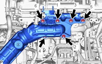
Tighten the 6 nuts in the sequence shown in the illustration.
- Torque:
- 26 N*m (265 kgf*cm, 19 ft.*lbf)
Connect the air fuel ratio sensor connector and attach the 2 wire harness clamps.
w/o Secondary Air Injection System:
Temporarily install the exhaust manifold assembly RH with the 5 nuts.
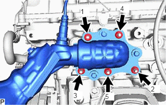
Tighten the 5 nuts in the sequence shown in the illustration.
- Torque:
- 26 N*m (265 kgf*cm, 19 ft.*lbf)
Connect the air fuel ratio sensor connector and attach the wire harness clamp.
17361N
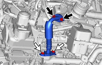
8.INSTALL NO. 1 AIR TUBE (w/ Secondary Air Injection System)
|
|
Bolt |
|
|
Nut |
Install 2 new gaskets and the No. 1 air tube to the exhaust manifold assembly RH and No. 1 emission control valve set with the 2 bolts and 2 nuts.
- Torque:
- 20 N*m (204 kgf*cm, 15 ft.*lbf)
- NOTICE:
-
Do not reuse the gasket.
11409
9.INSTALL ENGINE OIL LEVEL DIPSTICK GUIDE (w/ Secondary Air Injection System)
17118
10.INSTALL MANIFOLD STAY
Temporarily install the manifold stay to the transmission assembly and exhaust manifold assembly RH with the 3 bolts.
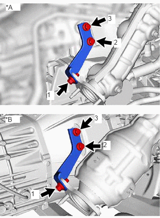
| *A | w/ Secondary Air Injection System |
| *B | w/o Secondary Air Injection System |
Tighten the 3 bolts in the sequence shown in the illustration.
- Torque:
- 40 N*m (408 kgf*cm, 30 ft.*lbf)
17450B
11.INSTALL FRONT NO. 2 EXHAUST PIPE ASSEMBLY
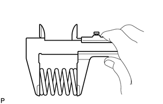
Using a vernier caliper, measure the free length of the compression spring.
- Minimum free length:
40.5 mm (1.59 in.)
If the free length is less than the minimum, replace the compression spring.
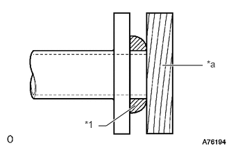
| *1 | Gasket |
| *a | Wooden Block |
Using a plastic-faced hammer and wooden block, tap in a new gasket until its surface is flush with the front exhaust pipe assembly.
- NOTICE:
- ·
Be sure to install the gasket so that it faces the correct direction.
·Do not reuse the gasket.
·Do not damage the gasket.
·When connecting the center exhaust pipe assembly, do not push in the gasket with the center exhaust pipe assembly.
Install the 2 new gaskets to the front No. 2 exhaust pipe assembly.
Install the front No. 2 exhaust pipe assembly with the 2 bolts, 2 compression springs and 2 new nuts.
- Torque:
- 43 N*m (438 kgf*cm, 32 ft.*lbf)
Connect the heated oxygen sensor connector and wire harness clamp.
17410
12.INSTALL FRONT EXHAUST PIPE ASSEMBLY
Install the 2 new gasket to the front exhaust pipe assembly.
Install the front exhaust pipe assembly with the 2 bolts and 2 new nuts.
- Torque:
- 43 N*m (438 kgf*cm, 32 ft.*lbf)
w/ Secondary Air Injection System:
Connect the heated oxygen sensor connector.
w/o Secondary Air Injection System:
Connect the heated oxygen sensor connector and wire harness clamp.
17403
13.INSTALL FRONT NO. 3 EXHAUST PIPE SUB-ASSEMBLY
14.INSPECT FOR EXHAUST GAS LEAK
If gas is leaking, tighten the areas necessary to stop the leak. Replace damaged parts as necessary.
51405A
15.INSTALL NO. 1 ENGINE UNDER COVER ASSEMBLY
52618
16.INSTALL LOWER FRONT BUMPER ABSORBER
51406A
17.INSTALL NO. 2 ENGINE UNDER COVER SUB-ASSEMBLY (w/ No. 2 Engine Under Cover Sub-assembly)