7GR-FKS ENGINE MECHANICAL CYLINDER HEAD GASKET INSTALLATION
PROCEDURE

 11115
1.INSTALL CYLINDER HEAD GASKET
11115
1.INSTALL CYLINDER HEAD GASKET
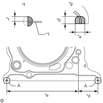
| *1 | Cylinder Head Gasket |
| *a | 7.0 to 9.0 mm (0.276 to 0.354 in.) |
| *b | 5.0 to 7.0 mm (0.197 to 0.276 in.) |
| *c | 3.0 to 5.0 mm (0.118 to 0.197 in.) |
| *d | 38.6 mm (1.52 in.) |
| *e | 142.7 mm (5.62 in.) |
| *f | Side View |
| *g | View A |
Apply seal packing to a new cylinder head gasket as shown in the illustration.
- Seal Packing:
Toyota Genuine Seal Packing Black, Three Bond 1207 B or equivalent
- NOTICE:
- ·
Be sure to clean and degrease the contact surfaces.
·Apply seal packing to the bead on the cylinder head gasket.
·Install the cylinder head gasket within 3 minutes and tighten the cylinder head set bolts within 15 minutes after applying seal packing.
·Do not apply engine oil within 2 hours of installation.
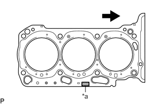
| *a | Lot No. |

|
Engine Front |
Place the cylinder head gasket on the cylinder block surface with the Lot No. stamp upward.
- NOTICE:
- ·
Be careful of the installation direction.
·Gently place the cylinder head sub-assembly in order not to damage the gasket with the bottom part of the head.
11101
2.INSTALL CYLINDER HEAD SUB-ASSEMBLY
- HINT:
-
Perform "Inspection After Repairs" after replacing the cylinder head sub-assembly.
Place the cylinder head sub-assembly on the cylinder block.
- NOTICE:
-
Be careful not to allow oil to adhere to the bottom part of the cylinder head sub-assembly.
- HINT:
-
The cylinder head bolts are tightened in 3 progressive steps.
Apply a light coat of engine oil to the threads and under the heads of the cylinder head bolts.
Step 1:
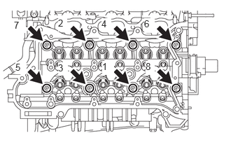
Using a 10 mm bi-hexagon wrench, install and uniformly tighten the 8 cylinder head bolts with the plate washers in several steps and in the sequence shown in the illustration.
- Torque:
- 36 N*m (367 kgf*cm, 27 ft.*lbf)
Step 2:
Mark the front side of each cylinder head bolt head with paint.
Tighten the cylinder head bolts another 90°.
Step 3:
Tighten the cylinder head bolts an additional 90°.
Check that the paint marks are now at a 180° angle to the front.
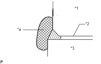
| *1 | Cylinder Head |
| *2 | Cylinder Head Gasket |
| *3 | Cylinder Block |
| *a | Wipe Clean |
Thoroughly wipe off seal packing that has seeped out onto the front side of the engine.
11116
3.INSTALL NO. 2 CYLINDER HEAD GASKET
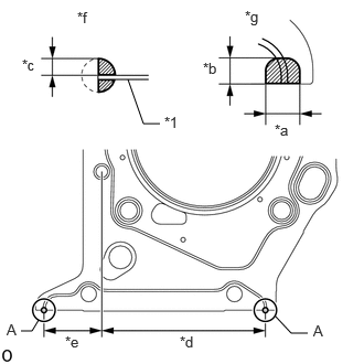
| *1 | Cylinder Head Gasket |
| *a | 7.0 to 9.0 mm (0.276 to 0.354 in.) |
| *b | 5.0 to 7.0 mm (0.197 to 0.276 in.) |
| *c | 3.0 to 5.0 mm (0.118 to 0.197 in.) |
| *d | 111.3 mm (4.38 in.) |
| *e | 39.3 mm (1.55 in.) |
| *f | Side View |
| *g | View A |
Apply seal packing to a new No. 2 cylinder head gasket as shown in the illustration.
- Seal Packing:
Toyota Genuine Seal Packing Black, Three Bond 1207 B or equivalent
- NOTICE:
- ·
Be sure to clean and degrease the contact surfaces.
·Apply seal packing to the bead on the No. 2 cylinder head gasket.
·Install the No. 2 cylinder head gasket within 3 minutes and tighten the cylinder head set bolts within 15 minutes after applying seal packing.
·Do not apply engine oil within 2 hours of installation.
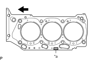
| *a | Lot No. |
|
|
Engine Front |
Place the No. 2 cylinder head gasket on the cylinder block surface with the Lot No. stamp upward.
- NOTICE:
- ·
Be careful of the installation direction.
·Gently place the cylinder head LH in order not to damage the gasket with the bottom part of the head.
11102
4.INSTALL CYLINDER HEAD LH
- HINT:
-
Perform "Inspection After Repairs" after replacing the cylinder head LH.
Place the cylinder head LH on the cylinder block.
- NOTICE:
-
Be careful not to allow oil to adhere to the bottom part of the cylinder head LH.
- HINT:
-
The cylinder head bolts are tightened in 3 progressive steps.
Apply a light coat of engine oil to the threads and under the heads of the cylinder head bolts.
Step 1:
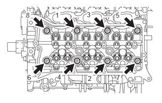
Using a 10 mm bi-hexagon wrench, install and uniformly tighten the 8 cylinder head bolts with the plate washers in several steps in the sequence shown in the illustration.
- Torque:
- 36 N*m (367 kgf*cm, 27 ft.*lbf)
Step 2:
Mark the front side of each cylinder head bolt head with paint.
Tighten the cylinder head bolts another 90°.
Step 3:
Tighten the cylinder head bolts an additional 90°.
Check that the paint marks are now at a 180° angle to the front.
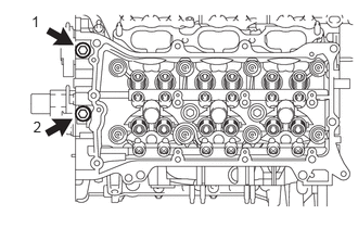
Tighten the 2 bolts in the order shown in the illustration.
- Torque:
- 30 N*m (306 kgf*cm, 22 ft.*lbf)
| *1 | Cylinder Head LH |
| *2 | No. 2 Cylinder Head Gasket |
| *3 | Cylinder Block |
| *a | Wipe Clean |
Thoroughly wipe off seal packing that has seeped out onto the front side of the engine.
23255A
5.INSTALL FUEL INJECTOR SEAL
23250E
6.INSTALL DIRECT FUEL INJECTOR ASSEMBLY
23814E
7.INSTALL FUEL DELIVERY PIPE RH
23860
8.INSTALL FUEL DELIVERY WITH SENSOR PIPE ASSEMBLY LH
23802B
9.INSTALL NO. 2 FUEL PIPE SUB-ASSEMBLY
16356
10.INSTALL REAR WATER BY-PASS JOINT
13716
11.INSTALL VALVE STEM CAP
Apply a light coat of engine oil to the valve stem caps.
Install the 24 valve stem caps to the cylinder head sub-assembly and cylinder head LH.
- NOTICE:
-
Install the valve stem cap to the same place it was removed from.
13750
12.INSTALL VALVE LASH ADJUSTER ASSEMBLY
Inspect the valve lash adjuster assembly.
Install the 24 valve lash adjuster assemblies to the cylinder head and cylinder head LH.
- NOTICE:
-
Install the lash adjuster to the same place it was removed from.
13801
13.INSTALL NO. 1 VALVE ROCKER ARM SUB-ASSEMBLY
Apply engine oil to the valve lash adjuster tips and valve stem cap ends.
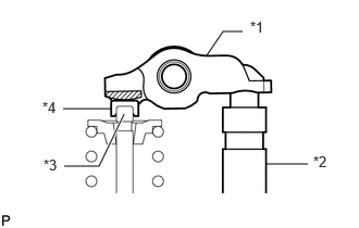
| *1 | Valve Rocker Arm |
| *2 | Valve Lash Adjuster Assembly |
| *3 | Valve Stem |
| *4 | Valve Stem Cap |
Install the 24 No. 1 valve rocker arm sub-assemblies as shown in the illustration.
- NOTICE:
-
Install the No. 1 valve rocker arm sub-assembly to the same place it was removed from.
13561
14.INSTALL NO. 1 CHAIN VIBRATION DAMPER
13562
15.INSTALL NO. 2 CHAIN VIBRATION DAMPER
13053
16.INSTALL NO. 3 CAMSHAFT SUB-ASSEMBLY
Apply a light coat of engine oil to the No. 3 camshaft journals and camshaft housing sub-assembly LH.
Install the No. 3 camshaft sub-assembly to the camshaft housing sub-assembly LH.
13054
17.INSTALL NO. 4 CAMSHAFT SUB-ASSEMBLY
Apply a light coat of engine oil to the No. 4 camshaft journals and camshaft housing sub-assembly LH.
Install the No. 4 camshaft sub-assembly to the camshaft housing sub-assembly LH.
18.INSTALL CAMSHAFT BEARING CAP (for Bank 2)
Apply engine oil to the camshaft bearing caps.
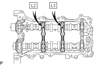
Make sure of the marks and numbers on the camshaft bearing caps and place each in the proper position and direction.
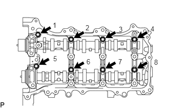
Temporarily install and tighten the 8 bolts in the order shown in the illustration.
- Torque:
- 10 N*m (102 kgf*cm, 7 ft.*lbf)
13560A
19.INSTALL NO. 3 CHAIN TENSIONER ASSEMBLY
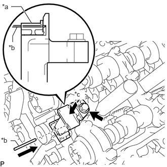
| *a | Plunger |
| *b | Pin |
| *c | Push |
Install the No. 3 chain tensioner assembly with the bolt.
- Torque:
- 21 N*m (214 kgf*cm, 15 ft.*lbf)
While pushing in the No. 3 chain tensioner assembly, insert a pin of 1.0 mm (0.0394 in.) diameter into the hole to fix the No. 3 chain tensioner in place.
20.TEMPORARILY INSTALL CAMSHAFT TIMING GEARS AND NO. 2 CHAIN SUB-ASSEMBLY (for Bank 2)
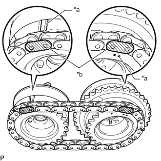
| *a | Timing Mark |
| *b | Mark Plate |
Align the mark plates (yellow) with the timing marks of the camshaft timing gear assemblies as shown in the illustration.
Align the knock pin of the camshaft with the pin hole of the camshaft timing gear assembly. Temporarily install the camshaft timing gear assembly and camshaft timing exhaust gear assembly with the No. 2 chain sub-assembly installed.
21.TEMPORARILY INSTALL CAMSHAFT TIMING GEAR BOLT (for Intake Side of Bank 2)
22.TEMPORARILY INSTALL CAMSHAFT TIMING GEAR BOLT (for Exhaust Side of Bank 2)
11104A
23.INSTALL CAMSHAFT HOUSING SUB-ASSEMBLY LH

| *1 | No. 1 Valve Rocker Arm Sub-assembly |
| *2 | Valve Lash Adjuster Assembly |
| *3 | Valve Stem |
| *4 | Valve Stem Cap |
| *a | CORRECT |
| *b | INCORRECT |
Make sure that the No. 1 valve rocker arm sub-assembly is installed as shown in the illustration.
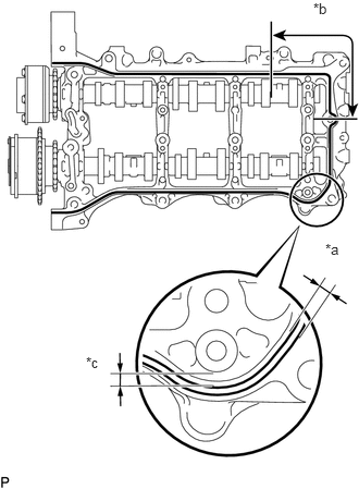
| *a | Diameter 3.0 to 4.0 mm (0.118 to 0.158 in.) |
| *b | Diameter 4.0 to 4.5 mm (0.158 to 0.177 in.) |
| *c | Clearance of 4.0 to 6.0 mm (0.158 to 0.236 in.) |

|
Seal Packing |
Apply seal packing in a continuous line as shown in the illustration.
- Seal packing:
Toyota Genuine Seal Packing Black, Three Bond 1207B or equivalent
- NOTICE:
- ·
Remove any oil from the contact surface.
·Install the camshaft housing sub-assembly LH within 3 minutes.
·Do not start the engine for at least 2 hours after installation.
Install the camshaft housing sub-assembly LH and tighten the 15 bolts in the order shown in the illustration.
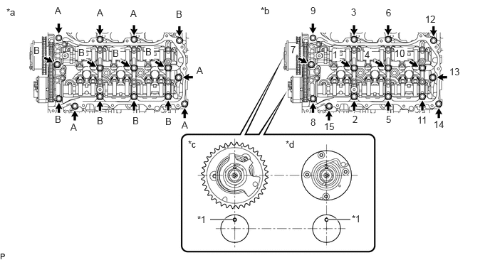
| *1 | Knock Pin | - | - |
| *a | Types of bolt | *b | Tightening order |
| *c | IN | *d | EX |
- Torque:
- 28 N*m (286 kgf*cm, 21 ft.*lbf)
- Standard Bolt:
Item Length A 48 mm (1.89 in.) B 68 mm (2.68 in.)
- NOTICE:
- ·
When installing the camshaft housing sub-assembly LH, it is necessary to correctly position the camshafts as shown in the illustration. Failure to correctly position these parts may result in damage due to contact between the pistons and valves. If a camshaft is rotated with a piston at TDC, valve contact will occur.
·If any of the bolts are loosened during installation, remove the camshaft housing sub-assembly LH, clean the installation surfaces, and reapply seal packing.
·If the camshaft housing sub-assembly LH is removed because any of the bolts are loosened during installation, make sure that the previously applied seal packing does not enter any oil passages.
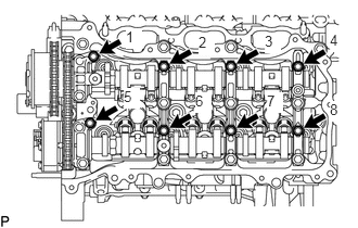
Tighten the 8 bolts in the order shown in the illustration.
- Torque:
- 16 N*m (163 kgf*cm, 12 ft.*lbf)
Remove any protruding seal packing black.
24.TIGHTEN CAMSHAFT TIMING GEAR BOLT (for Bank 2)
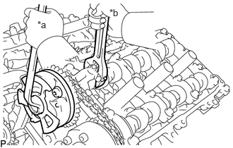
| *a | Turn |
| *b | Hold |
Using a wrench to hold the hexagonal portion of each camshaft, tighten the camshaft timing gear bolts of the camshaft timing gear assembly.
- Torque:
- 95 N*m (969 kgf*cm, 70 ft.*lbf)
- NOTICE:
-
Be careful not to damage the camshaft housing sub-assembly LH or spark plug tube with the wrench.
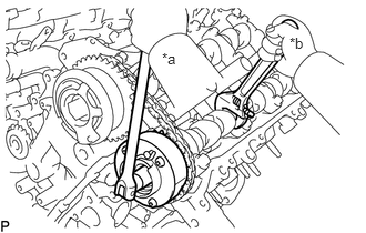
| *a | Turn |
| *b | Hold |
Using a wrench to hold the hexagonal portion of each camshaft, tighten the camshaft timing gear bolts of the camshaft timing exhaust gear assembly.
- Torque:
- 95 N*m (969 kgf*cm, 70 ft.*lbf)
- NOTICE:
-
Be careful not to damage the camshaft housing sub-assembly LH or spark plug tube with the wrench.
Remove the pin from the No. 3 chain tensioner assembly.
13511
25.INSTALL CAMSHAFT
Apply a light coat of engine oil to the camshaft journals and camshaft housing sub-assembly RH.
Install the camshaft to the camshaft housing sub-assembly RH.
13512
26.INSTALL NO. 2 CAMSHAFT
Apply a light coat of engine oil to the No. 2 camshaft journals and camshaft housing sub-assembly RH.
Install the No. 2 camshaft to the camshaft housing sub-assembly RH.
23476
27.INSTALL FUEL PUMP LIFTER HOUSING
Install the fuel pump lifter housing.
28.INSTALL CAMSHAFT BEARING CAP (for Bank 1)
Apply engine oil to the camshaft bearing caps.
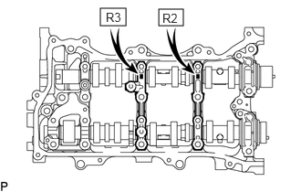
Make sure of the marks and numbers on the camshaft bearing caps and place each in the proper position and direction.
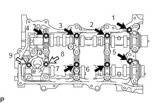
|
|
Bolt A |

|
Bolt B |
Temporarily install and tighten the 9 camshaft bearing cap bolts in the order shown in the illustration.
- Torque:
- 10 N*m (102 kgf*cm, 7 ft.*lbf)
- Standard Bolt:
Item Length A 40 mm (1.57 in.) B 58 mm (2.28 in.)
13550
29.INSTALL NO. 2 CHAIN TENSIONER ASSEMBLY
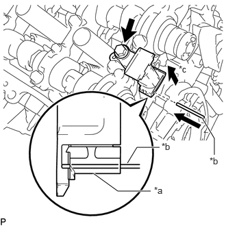
| *a | Plunger |
| *b | Pin |
| *c | Push |
Install the No. 2 chain tensioner assembly with the bolt.
- Torque:
- 21 N*m (214 kgf*cm, 15 ft.*lbf)
While pushing in the No. 2 chain tensioner assembly, insert a pin of 1.0 mm (0.0394 in.) diameter into the hole to fix the No. 2 chain tensioner assembly in place.
30.TEMPORARILY INSTALL CAMSHAFT TIMING GEARS AND NO. 2 CHAIN SUB-ASSEMBLY (for Bank 1)
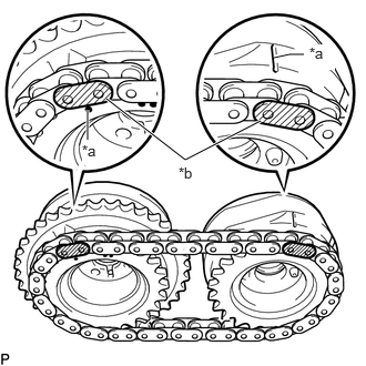
| *a | Timing Mark |
| *b | Mark Plate |
Align the mark plates (yellow) with the timing marks of the camshaft timing gear assemblies as shown in the illustration.
Align the knock pin of the camshaft with the pin hole of the camshaft timing gear assembly. Temporarily install the camshaft timing gear assembly and camshaft timing exhaust gear assembly with the No. 2 chain sub-assembly installed.
31.TEMPORARILY INSTALL CAMSHAFT TIMING GEAR BOLT (for Intake Side of Bank 1)
32.TEMPORARILY INSTALL CAMSHAFT TIMING GEAR BOLT (for Exhaust Side of Bank 1)
11103C
33.INSTALL CAMSHAFT HOUSING SUB-ASSEMBLY RH
| *1 | No. 1 Valve Rocker Arm Sub-assembly |
| *2 | Valve Lash Adjuster Assembly |
| *3 | Valve Stem |
| *4 | Valve Stem Cap |
| *a | CORRECT |
| *b | INCORRECT |
Make sure that the No. 1 valve rocker arm sub-assembly is installed as shown in the illustration.
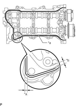
| *a | Diameter 3.0 to 4.0 mm (0.118 to 0.158 in.) |
| *b | Clearance of 4.0 to 6.0 mm (0.158 to 0.236 in.) |
|
|
Seal Packing |
Apply seal packing in a continuous line as shown in the illustration.
- Seal packing:
Toyota Genuine Seal Packing Black, Three Bond 1207B or equivalent
- NOTICE:
- ·
Remove any oil from the contact surface.
·Install the camshaft housing sub-assembly RH within 3 minutes.
·Do not start the engine for at least 2 hours after installation.
Install the camshaft housing sub-assembly RH and tighten the 15 bolts in the order shown in the illustration.
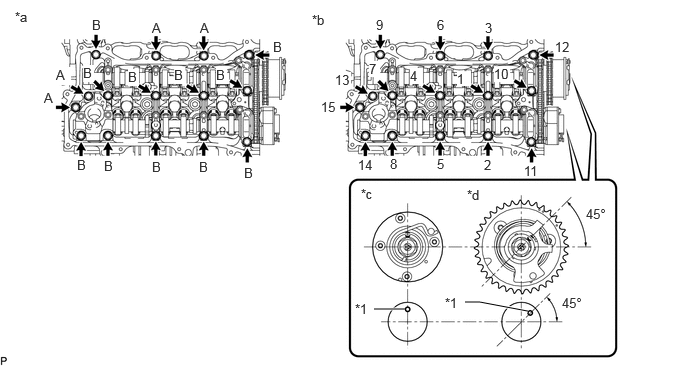
| *1 | Knock Pin | - | - |
| *a | Types of bolt | *b | Tightening order |
| *c | EX | *d | IN |
- Torque:
- 28 N*m (286 kgf*cm, 21 ft.*lbf)
- Standard Bolt:
Item Length A 48 mm (1.89 in.) B 68 mm (2.68 in.)
- NOTICE:
- ·
When installing the camshaft housing sub-assembly RH, it is necessary to correctly position the camshafts as shown in the illustration.
Failure to correctly position these parts may result in damage due to contact between the pistons and valves. If a camshaft is rotated with a piston at TDC, valve contact will occur.
·If any of the bolts are loosened during installation, remove the camshaft housing sub-assembly RH, clean the installation surfaces, and reapply seal packing.
·If the camshaft housing sub-assembly RH is removed because any of the bolts are loosened during installation, make sure that the previously applied seal packing does not enter any oil passages.
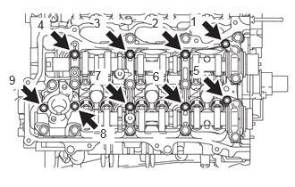
Tighten the 9 bolts in the order shown in the illustration.
- Torque:
- 16 N*m (163 kgf*cm, 12 ft.*lbf)
Remove any protruding seal packing black.
34.TIGHTEN CAMSHAFT TIMING GEAR BOLT (for Bank 1)
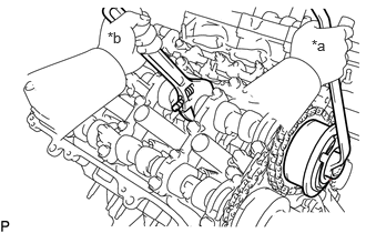
| *a | Turn |
| *b | Hold |
Using a wrench to hold the hexagonal portion of each camshaft, tighten the camshaft timing gear bolts of the camshaft timing gear assembly.
- Torque:
- 95 N*m (969 kgf*cm, 70 ft.*lbf)
- NOTICE:
-
Be careful not to damage the camshaft housing sub-assembly RH or spark plug tube with the wrench.
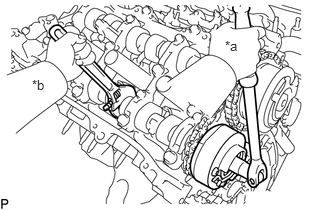
| *a | Turn |
| *b | Hold |
Using a wrench to hold the hexagonal portion of each camshaft, tighten the camshaft timing gear bolts of the camshaft timing exhaust gear assembly RH.
- Torque:
- 95 N*m (969 kgf*cm, 70 ft.*lbf)
- NOTICE:
-
Be careful not to damage the camshaft housing sub-assembly RH or spark plug tube with the wrench.
Remove the pin from the No. 2 chain tensioner assembly.
13506
35.INSTALL CHAIN SUB-ASSEMBLY
13559
36.INSTALL CHAIN TENSIONER SLIPPER
13540
37.INSTALL NO. 1 CHAIN TENSIONER ASSEMBLY
38.INSPECT VALVE TIMING
11310
39.INSTALL TIMING CHAIN COVER ASSEMBLY