FRONT SUSPENSION FRONT LOWER SUSPENSION ARM INSTALLATION
CAUTION / NOTICE / HINT
- HINT:
- ·
Use the same procedure for the RH side and LH side.
·The following procedure is for the LH side.
PROCEDURE

 48069
1.TEMPORARILY INSTALL FRONT LOWER NO. 1 SUSPENSION ARM SUB-ASSEMBLY
48069
1.TEMPORARILY INSTALL FRONT LOWER NO. 1 SUSPENSION ARM SUB-ASSEMBLY
Temporarily install the front lower No. 1 suspension arm sub-assembly LH to the front frame assembly with the 2 bolts and 2 nuts.
Temporarily install the front lower No. 1 suspension arm sub-assembly LH to the front axle assembly with the nut.
2.STABILIZE SUSPENSION
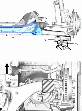
| *a | Wooden Block |
| *b | Jack |

|
Wooden Block Placement Location |
Using a jack and wooden block, apply load to the suspension so that the front lower No. 1 suspension arm sub-assembly is positioned as shown in the illustration.
- Standard Length (A):
31 to 41 mm (1.221 to 1.614 in.)
- CAUTION:
-
Do not jack up the front lower No. 1 suspension arm sub-assembly too high as the vehicle may fall.
- NOTICE:
- ·
When jacking up the front lower No. 1 suspension arm sub-assembly, be sure to jack it up slowly.
·Make sure to perform this operation with the vehicle kept as low as possible.
48069
3.INSTALL FRONT LOWER NO. 1 SUSPENSION ARM SUB-ASSEMBLY
Install the front lower No. 1 suspension arm sub-assembly (front frame assembly side) with the 2 bolts and 2 nuts.
- Torque:
- 270 N*m (2753 kgf*cm, 199 ft.*lbf)
Install the front lower No. 1 suspension arm sub-assembly (front axle assembly side) with the nut.
- Torque:
- 125 N*m (1275 kgf*cm, 92 ft.*lbf)
- NOTICE:
- ·
Do not apply lubricants to the ball joint stud taper and threads.
·Remove any foreign matter from the contact surface of the steering knuckle and front lower No. 1 suspension arm sub-assembly stud taper.
Install a new cotter pin.
- NOTICE:
-
Further tighten the nut up to 60° if the holes for the cotter pin are not aligned.
43212
4.INSTALL STEERING KNUCKLE
Install the steering knuckle to the from the front shock absorber assembly with the 2 bolts and 2 nuts.
- Torque:
- 290 N*m (2957 kgf*cm, 214 ft.*lbf)
- NOTICE:
- ·
When installing the bolts, keep the nuts from rotating.
·Do not apply lubricants to the steering knuckle and shock absorber contact surfaces.
43512
5.INSTALL FRONT DISC
6.CONNECT FRONT DISC BRAKE CALIPER ASSEMBLY
89543
7.INSTALL FRONT SPEED SENSOR
45047
8.CONNECT TIE ROD END SUB-ASSEMBLY
51108C
9.INSTALL REAR SIDE RAIL REINFORCEMENT SUB-ASSEMBLY
51408B
10.INSTALL ENGINE UNDER COVER SUB-ASSEMBLY RH (w/ Engine Under Cover Sub-assembly RH)
51495
11.INSTALL TRANSMISSION UNDER COVER (w/ Transmission Under Cover)
51405A
12.INSTALL NO. 1 ENGINE UNDER COVER SUB-ASSEMBLY
52618
13.INSTALL LOWER FRONT BUMPER ABSORBER
51406A
14.INSTALL NO. 2 ENGINE UNDER COVER SUB-ASSEMBLY (w/ No. 2 Engine Under Cover Sub-assembly)
15.INSTALL FRONT WHEEL
16.INSPECT AND ADJUST FRONT WHEEL ALIGNMENT
17.CHECK ABS SPEED SENSOR SIGNAL
18.PERFORM INITIALIZATION
| Parking assist monitor system | ( 201902,202310,_56,_079315,_0385736,RM100000001GNRB,202310,999999,_56,_079315,_0385736,RM100000002G5JM,) 201902,202310,_56,_079315,_0385736,RM100000001GNRB,202310,999999,_56,_079315,_0385736,RM100000002G5JM,)
|
| Panoramic view monitor system | (201906,202310,_56,_079315,_0396274,RM100000001IGR4,202310,999999,_56,_079315,_0396274,RM100000002G5L7,)
|
| Lighting system (EXT) | (201906,999999,_59,_079256,_0396321,RM100000001IGX8,)
|