FRONT SUSPENSION FRONT SHOCK ABSORBER INSTALLATION
CAUTION / NOTICE / HINT
- HINT:
- ·
Use the same procedure for the RH side and LH side.
·The following procedure is for the LH side.
PROCEDURE

 48158C
1.INSTALL FRONT LOWER COIL SPRING INSULATOR
48158C
1.INSTALL FRONT LOWER COIL SPRING INSULATOR
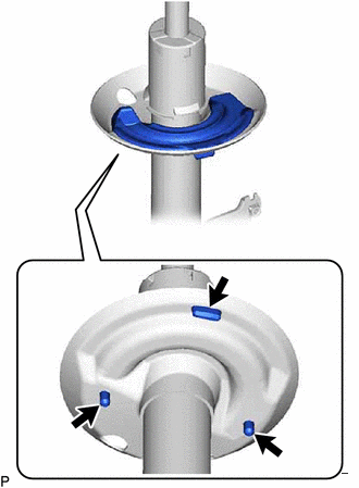

|
Positioning Pin |
Install the front lower coil spring insulator to the front shock absorber assembly.
- NOTICE:
-
When installing the front lower coil spring insulator, insert the positioning pin of the spring seat into the hole of the front lower coil spring insulator.
48132
2.INSTALL FRONT COIL SPRING
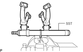
Secure SST in a vise.
- SST
- 09727-00051
09727-30022 (09727-00010, 09727-00031)
Attach the hooks of each SST arm across the diameter of the coil spring.
- CAUTION:
- ·
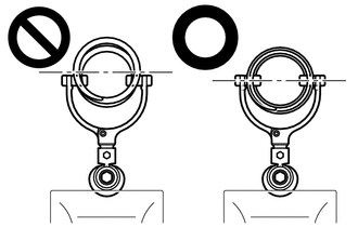
Make sure that the hooks are securely attached to the coil spring.
·If a hook disengages from the coil spring, the coil spring may fly out, resulting in injury.
·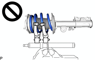
Make sure that the hooks of the upper and lower SST arms are attached to the coil spring so that the distance between the hooks is as large as possible.
·If a hook disengages from the coil spring, the coil spring may fly out, resulting in injury.
·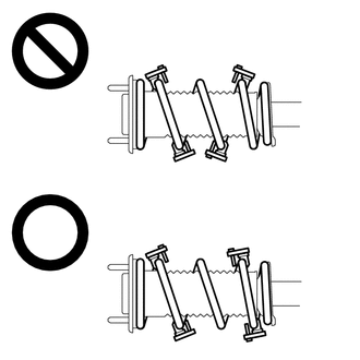
Make sure that the arms of SST are parallel and the number of coils between the arms is the same on each side.
·If a hook disengages from the coil spring, the coil spring may fly out, resulting in injury.
Install the stopper pins to the hooks of SST.
- CAUTION:
-
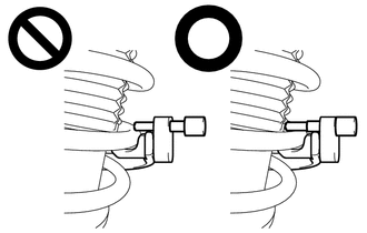
- ·
Make sure that the stopper pins are installed securely.
·If a hook disengages from the coil spring, the coil spring may fly out, resulting in injury.
Using SST, compress the coil spring.
- CAUTION:
- ·
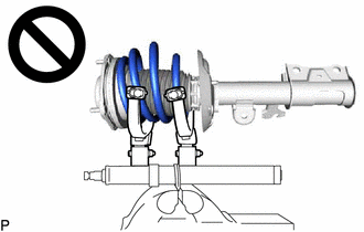
If the coil spring starts to bow out while using SST, stop immediately and reattach SST correctly.
·If a hook disengages from the coil spring, the coil spring may fly out, resulting in injury.
·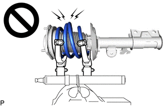
Do not compress the coil spring to the point where the coils touch each other.
·If a hook disengages from the coil spring, the coil spring may fly out, resulting in injury.
·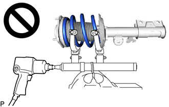
Do not use an impact wrench.
·If an impact wrench is used, the threads of SST may be damaged, or sudden compression of the coil spring may cause a hook to disengage and the coil spring to fly out, resulting in injury.
·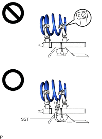 1.021,4 1.854,4 true 0.708,3.927 1.208,4.177 0.5,0.25 10 false SST
If a stopper pin touches the coil spring while using SST, remove the stopper pin and continue with the procedure.
·If a stopper pin is removed, install a coil spring stopper belt as shown in the illustration.
·If a hook disengages from the coil spring, the coil spring may fly out, resulting in injury.
- SST
- 09727-00110
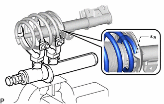
| *a | Depression |
Align the end of the front coil spring with the flange of the front lower coil spring insulator and install the front coil spring.
- NOTICE:
-
Make sure to fit the end of the front coil spring that has the larger diameter into the depression of the front lower coil spring insulator.
48619A
3.INSTALL STRUT MOUNTING BEARING
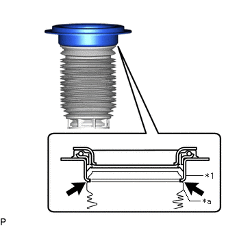
| *1 | Strut Mounting Bearing |
| *a | Top End of the Front No. 1 Shock Absorber Dust Cover |
Install the strut mounting bearing to the front No. 1 shock absorber dust cover.
- NOTICE:
-
Make sure that the top end of the front No. 1 shock absorber dust cover and strut mounting bearing are securely attached.
48157C
4.INSTALL FRONT UPPER COIL SPRING INSULATOR
Install the front upper coil spring insulator to the strut mounting bearing.
5.INSTALL STRUT MOUNTING BEARING WITH DUST COVER
Install the strut mounting bearing with dust cover to the front shock absorber assembly.
48331C
6.INSTALL FRONT SPRING BUMPER
Install the front spring bumper to the front suspension support sub-assembly.
- NOTICE:
- ·
Face the smaller diameter end of the front spring bumper downward.
·Do not apply lubricants to the front spring bumper.
·Do not clean the front spring bumper with water or solvent.
48609
7.INSTALL FRONT SUSPENSION SUPPORT SUB-ASSEMBLY
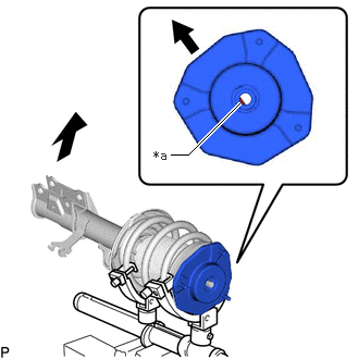
| *a | Slot |
|
|
Outside of the Vehicle |
Install the front suspension support sub-assembly as shown in the illustration.
- NOTICE:
-
Check that the slot on the piston rod and the slot on the front suspension support sub-assembly are aligned.
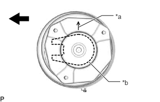
| *a | Arrow of Front Suspension Support Sub-assembly |
| *b | Front Shock Absorber Lower Bracket |
|
|
Outside of the Vehicle |
Align the arrow of the front suspension support sub-assembly with the front shock absorber lower bracket as shown in the illustration.
48680A
8.TEMPORARILY TIGHTEN FRONT SUPPORT TO FRONT SHOCK ABSORBER NUT
Temporarily tighten a new front support to front shock absorber nut.
Remove SST from the front coil spring.
- NOTICE:
-
Do not use an impact wrench. It will damage SST.
48559B
9.INSTALL FRONT NO. 1 SHOCK ABSORBER DUST COVER
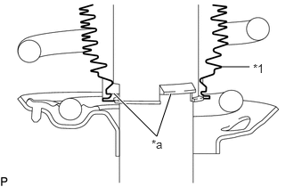
| *1 | Front No. 1 Shock Absorber Dust Cover |
| *a | Claw |
Install the end of the front No. 1 shock absorber dust cover with the claws of the front shock absorber assembly.
- NOTICE:
- ·
Make sure that the end of the front No. 1 shock absorber dust cover is securely attached to the claws of the front shock absorber assembly.
·Make sure there is no excessive damage to the bellows of the front No. 1 shock absorber dust cover.
·Do not allow oil, grease, etc., to install the front No. 1 shock absorber dust cover.
·If there is oil or grease on the insulator, wipe clean with a cloth. Do not use an alcohol based cleaner.
10.INSTALL FRONT SHOCK ABSORBER WITH COIL SPRING
Install the front shock absorber with coil spring (upper side) with the 3 nuts.
- Torque:
- 50 N*m (510 kgf*cm, 37 ft.*lbf)
Install the front shock absorber with coil spring (lower side) to the steering knuckle with the 2 bolts and 2 nuts.
- Torque:
- 290 N*m (2957 kgf*cm, 214 ft.*lbf)
- NOTICE:
- ·
Insert the bolt from the front of the vehicle.
·When installing the bolts, keep the nuts from rotating.
·Do not apply lubricants to the steering knuckle and shock absorber contact surfaces.
48680A
11.FULLY TIGHTEN FRONT SUPPORT TO FRONT SHOCK ABSORBER NUT
Fully tighten the front support to front shock absorber nut.
- Torque:
- 65 N*m (663 kgf*cm, 48 ft.*lbf)
- NOTICE:
-
Perform this step only when the front shock absorber with coil spring has been disassembled.
89543
12.INSTALL FRONT SPEED SENSOR
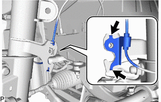
|
|
Hook |
Engage the 2 hooks to install the front speed sensor clamp bracket.
- NOTICE:
-
Do not twist the front speed sensor when installing it.
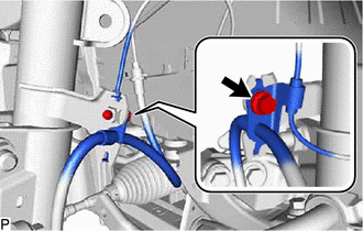
Install the front speed sensor and front flexible hose to the front shock absorber assembly with the bolt.
- Torque:
- 25 N*m (255 kgf*cm, 18 ft.*lbf)
- NOTICE:
-
Do not twist the front flexible hose when installing it.
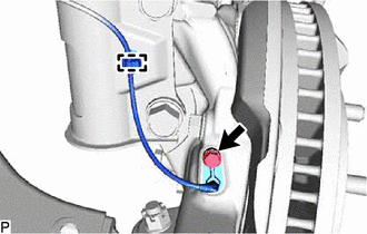
Install the front speed sensor to the steering knuckle with the bolt.
- Torque:
- 8.5 N*m (87 kgf*cm, 75 in.*lbf)
- NOTICE:
- ·
Prevent foreign matter from attaching to the front speed sensor tip.
·Firmly insert the front speed sensor body into the steering knuckle before tightening the bolt.
·After installing the front speed sensor to the steering knuckle, make sure that there is no clearance between the front speed sensor stay and steering knuckle. Also make sure that no foreign matter is stuck between the parts.
·Do not twist the front speed sensor when installing it.
Engage the clamp.
- NOTICE:
-
Do not twist the front speed sensor when installing it.
48810
13.INSTALL FRONT STABILIZER LINK ASSEMBLY
14.INSTALL FRONT WHEEL
17705
15.INSTALL AIR CLEANER CAP SUB-ASSEMBLY (for RH Side)
for 7GR-FKS:
Engage the 2 guides and install the air cleaner cap sub-assembly to the air cleaner case sub-assembly.
Engage the 2 air cleaner cap clamps.
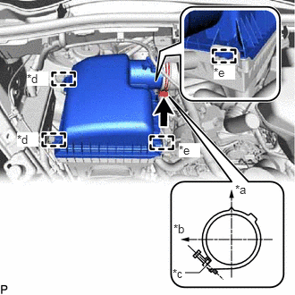
| *a | Upper Side of the Vehicle |
| *b | Front of the Vehicle |
| *c | Stopper |
| *d | Air Cleaner Cap Clamp |
| *e | Guide |
Connect the air cleaner hose assembly to the air cleaner hose and tighten the clamp.
- Torque:
- 4.0 N*m (41 kgf*cm, 35 in.*lbf)
- HINT:
-
Make sure the hose clamp is oriented as shown in the illustration.
Connect the mass air flow meter connector.
Engage the 2 wire harness clamps.
for 1GD-FTV:
Engage the 2 guides and install the air cleaner cap sub-assembly to the air cleaner case sub-assembly.
Engage the 2 air cleaner cap clamps.
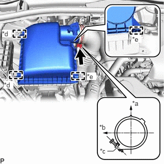
| *a | Upper Side of the Vehicle |
| *b | Front of the Vehicle |
| *c | Stopper |
| *d | Air Cleaner Cap Clamp |
| *e | Guide |
Connect the air cleaner hose assembly to the air cleaner hose and tighten the clamp.
- Torque:
- 4.0 N*m (41 kgf*cm, 35 in.*lbf)
- HINT:
-
Make sure the hose clamp is oriented as shown in the illustration.
Connect the mass air flow meter connector.
Engage the wire harness clamp.
16.INSPECT AND ADJUST FRONT WHEEL ALIGNMENT
17.CHECK ABS SPEED SENSOR SIGNAL
18.PERFORM INITIALIZATION
| Parking assist monitor system | ( 201902,202310,_56,_079315,_0385736,RM100000001GNRB,202310,999999,_56,_079315,_0385736,RM100000002G5JM,) 201902,202310,_56,_079315,_0385736,RM100000001GNRB,202310,999999,_56,_079315,_0385736,RM100000002G5JM,)
|
| Panoramic view monitor system | (201906,202310,_56,_079315,_0396274,RM100000001IGR4,202310,999999,_56,_079315,_0396274,RM100000002G5L7,)
|
| Lighting system (EXT) | (201906,999999,_59,_079256,_0396321,RM100000001IGX8,)
|