STOP AND START STOP AND START SYSTEM P160300 Engine Stall History
DESCRIPTION
If the engine stalls or fails to start while stop and start control is operating, DTC P160300 will be stored. Using the GTS, the freeze frame data recorded the moment the DTC is stored can be read. Serviceability has been enhanced by enabling the cause of an engine stall or engine start failure which occurred while stop and start control was operating to be checked using the freeze frame data.
| DTC No. | Detection Item | DTC Detection Condition | Trouble Area | Warning Indicate | Memory | Note |
|---|---|---|---|---|---|---|
| P160300 | Engine Stall History | Both of the following conditions are met for 0.5 seconds or more (1 trip detection logic):
·
Engine stopped by stop and start control and engine hood opened. ·
Engine hood courtesy switch (hood lock assembly): Engine hood opened and mode changed to "stalled"*1. Both of the following conditions are met for 0.5 seconds or more (1 trip detection logic): ·
Engine stopped by stop and start control and collision or low battery voltage detected. ·
Collision detection signal received from the airbag sensor assembly and mode changed to "stalled"*1. Both of the following conditions are met for 0.5 seconds or more (1 trip detection logic): ·
Engine being restarted by stop and start control and collision detected. ·
Collision detection signal received from the airbag sensor assembly and mode changed to "stalled"*1. Both of the following conditions are met for 0.5 seconds or more (1 trip detection logic): ·
Engine being restarted by stop and start control and restart fails. ·
Using the NE signal, complete combustion is identified 0.6 seconds after the engine stop judgment*2 was made or complete combustion does not occur even after the starter assembly has operated for a certain amount of time (NE signal is normal). Both of the following conditions are met for 0.5 seconds or more (1 trip detection logic): ·
Engine being restarted by stop and start control and restart fails. ·
Engine speed signal from the ECM not received via CAN communication (NE signal is abnormal*3). Detection Conditions: Always Sensors/components used for detection: engine hood courtesy switch (hood lock assembly), neutral position switch (for Manual Transmission), park/neutral position switch assembly (for Automatic Transmission), airbag sensor assembly, battery, crank position sensor, STA signal circuit, ECM |
·
Wire harness or connector ·
Engine hood courtesy switch (Hood lock assembly) ·
CAN communication system ·
Airbag system ·
ECD system ·
Starter assembly ·
Engine stop and start ECU |
Does not come on | DTC stored | SAE Code: P1603 |
*1: The mode "stalled" represents a state in which engine restart is prohibited/canceled due to a collision being detected or the engine hood being opened and restart is not preferable. In this situation, "IG" is displayed for the Data List item [Stop&Start of Eng State]. If the mode changes to "IG", engine start by stop and start control is prohibited and the engine can only be started by operating the ignition switch (w/o Entry and Start System) or push start switch assembly (w/ Entry and Start System).
*2: Engine stop judgment is performed to judge whether the engine is stopped completely. The engine stop and start ECU judges that the engine is stopped when it does not receive an engine speed signal (NE signal) from the ECM for 0.6 seconds or more.
*3: The engine stop and start ECU stores DTC P033562.
WIRING DIAGRAM
Refer to Engine Hood Courtesy Switch Circuit.
Refer to DTC P061519.
CAUTION / NOTICE / HINT
- NOTICE:
- ·
Before replacing the engine stop and start ECU, read the number of starter operations and write it into a new engine stop and start ECU.
·After replacing the engine stop and start ECU or air conditioning amplifier assembly, reset and perform learning of the air conditioning information in the engine stop and start ECU.
·After replacing the engine stop and start ECU or airbag sensor assembly, clear and calibrate the deceleration sensor zero point in the engine stop and start ECU.
·for Automatic Transmission:
When the engine stop and start ECU or electromagnetic oil pump is replaced, check the electromagnetic oil pump.
·After replacing the starter assembly, perform initialization of the number of starter operations stored in the engine stop and start ECU.
·When the starter assembly is replaced, "STARTER relay" and "STARTER NO.2 relay" must be also replaced.
·Inspect the fuses for circuits related to this system before performing the following procedure.
- HINT:
- ·
If other DTCs are output, perform troubleshooting for this DTC first.
·Unlike other DTCs that are stored due to a malfunction in parts, circuits or systems, DTC P160300 allows determination of a malfunctioning part according to problem symptoms and freeze frame data related to a problem recognized by the customer. As this DTC may be stored due to an operation by the customer, it is not necessary to service the vehicle unless the customer recognized a problem. Clear the DTCs and return the vehicle to the customer.
·Using the GTS, read the freeze frame data before troubleshooting. System condition information is recorded as freeze frame data the moment a DTC is stored. This information can be useful when troubleshooting.
·DTCs for the stop and start system are not cleared even if the malfunction has been repaired. After repairing the malfunction, be sure to clear the DTCs.
·Stop and Start Control Mode Transition:
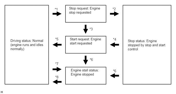 0.427,1.563 1.844,2.156 1.417,0.594 10 false Driving status: Normal (engine runs and idles normally) 5.208,1.573 6.833,2.094 1.625,0.521 10 false Stop status: Engine stopped by stop and start control 2.813,0.25 4.156,0.615 1.344,0.365 10 false Stop request: Engine stop requested 2.844,1.5 4.208,1.833 1.365,0.333 10 false Start request: Engine start requested 2.885,2.76 4.094,3.115 1.208,0.354 10 false Engine stall status: Engine stopped 2.229,0.292 2.542,0.49 0.313,0.198 10 false *1 4.604,2.792 4.917,2.99 0.313,0.198 10 false *6 2.25,1.5 2.563,1.698 0.313,0.198 10 false *5 2.25,2.5 2.563,2.698 0.313,0.198 10 false *7 2.25,3.042 2.563,3.24 0.313,0.198 10 false *8 4.583,0.281 4.896,0.479 0.313,0.198 10 false *2 4.604,1.51 4.917,1.708 0.313,0.198 10 false *4 3.646,1.094 3.958,1.292 0.313,0.198 10 false *3 3.656,2.333 3.969,2.531 0.313,0.198 10 false *6
*1: Engine stop conditions are met.
*2: Engine stop judgment is determined.
*3: Engine start conditions are met before the engine is judged as stopped.
*4: Engine start conditions are met.
*5: Engine determined to be started (engine speed reaches a specified rpm).
*6: Collision detected or engine hood opened and mode changed to "stalled".
*7: 0.6 seconds elapse after engine stop judgment is established.
*8: Engine is started using the ignition switch (w/o Entry and Start System) or push start switch assembly (w/ Entry and Start System).
PROCEDURE
Connect the GTS to the DLC3.
Turn the ignition switch to ON.
Turn the GTS on.
Enter the following menus: Powertrain / Engine / Trouble Codes.
Read the DTCs.
- Powertrain > Engine > Trouble Codes
- 50001 372
- Result:
Result Proceed to ECD system DTCs are not output A ECD system starting malfunction circuit DTC is output and starter assembly does not operate ECD system starting malfunction circuit DTC is output and starter assembly operates B DTCs other than ECD system starting malfunction circuit DTC are output
- HINT:
- ·
According to the display on the GTS, check the freeze frame data item [Cranking Time] in the sets of freeze frame data.
·If the value of [Cranking Time] is approximately 3 seconds, the stop and start control system or starter system may be malfunctioning.
·If the value of [Cranking Time] is small (approximately 0.5 seconds or less: the minimum value varies depending on the model), the ECD system may be malfunctioning.
·The Data List item [Cranking Time] indicates the length of time starter operation is requested by the engine stop and start ECU. If the engine speed exceeds the specified value, the engine stop and start ECU cancels its start request.
A
B
- NOTICE:
-
The freeze frame data is cleared when DTCs are cleared. Be sure to make a note of necessary data in advance.
- HINT:
-
Using the time-series freeze frame data, confirm the freeze frame data recorded the moment the DTC was stored and after the DTC was stored. This information can be useful when troubleshooting.
According to the prompts on the GTS screen, read the time-series freeze frame data to confirm the vehicle conditions when an engine stall occurred while stop and start control was operating.
Check the freeze frame data for engine stall history and engine start failure.
- Result:
GTS Display Result Proceed to Engine Stall History during Stop&Start (Hood Open) Yes A Engine Stall History during Stop&Start (Collision or Battery Voltage Low) Yes B Engine Stall History during Engine Starting (Collision) Yes Engine Start Fail Yes C
A
B
C
- NOTICE:
-
Before performing this step, check that the engine hood can be opened by pulling the hood lock control cable.
Connect the GTS to the DLC3.
Turn the ignition switch to ON.
Turn the GTS on.
Enter the following menus: Powertrain / Stop and Start / Data List / Hood Courtesy Switch.
- Powertrain > Stop and Start > Data List
-
Tester Display Hood Courtesy Switch - 50003 392 207
According to the display on the GTS, read the Data List.
- OK:
GTS Display Condition Normal Condition Hood Courtesy Switch Engine hood closed ON Engine hood open OFF
- Result:
Proceed to OK NG
OK
NG
Inspect the engine hood courtesy switch (hood lock assembly).
- Result:
Proceed to OK NG
OK
NG
Disconnect the engine hood courtesy switch (hood lock assembly) connector.
Measure the resistance according to the value(s) in the table below.
- Standard Resistance:
Tester Connection Condition Specified Condition A11-2 (E) - Body ground Always Below 1 Ω
- Result:
Proceed to OK NG
OK
NG
Disconnect the engine stop and start ECU connector.
Disconnect the engine hood courtesy switch (hood lock assembly) connector.
Measure the resistance according to the value(s) in the table below.
- Standard Resistance:
Tester Connection Condition Specified Condition N32-7 (BNT1) - A11-1 (+) Always Below 1 Ω N32-7 (BNT1) or A11-1 (+) - Body ground and other terminals Always 10 kΩ or higher
- Result:
Proceed to OK NG
OK
NG
Check if the vehicle was in a collision when the engine stalled.
- Result:
Result Proceed to Vehicle was in collision when engine stalled A Vehicle was not in collision when engine stalled B
- HINT:
-
When "Engine Stall History during Stop&Start (Collision or Battery Voltage Low)" or "Engine Stall History during Engine Starting (Collision)" is stored:
-
This may have been stored because the vehicle was in a collision or a collision detection signal was input while stop and start control was operating.
A
B
Disconnect the engine stop and start ECU connector.
Remove the STARTER relay and STARTER NO.2 relay from the No. 1 engine room relay block and No. 1 junction block assembly.
w/ Entry and Start System:
Disconnect the certification ECU (smart key ECU assembly) connector.
for Automatic Transmission:
Disconnect the park/neutral position switch assembly connector.
for Manual Transmission:
Disconnect the clutch start switch assembly (for lower) connector.
Disconnect the ECM connector.
Measure the resistance according to the value(s) in the table below.
- Standard Resistance:
Tester Connection Condition Specified Condition N32-21 (STA) - 2 (STARTER relay) Always Below 1 Ω N32-23 (STA2) - 2 (STARTER NO.2 relay) Always Below 1 Ω N32-21 (STA) or 2 (STARTER relay) - Body ground and other terminals Always 10 kΩ or higher N32-23 (STA2) or 2 (STARTER NO.2 relay) - Body ground and other terminals Always 10 kΩ or higher
- Result:
Proceed to OK NG
OK
NG
Remove the STARTER relay and STARTER NO.2 relay from the No. 1 engine room relay block and No. 1 junction block assembly.
Measure the resistance according to the value(s) in the table below.
- Standard Resistance:
Tester Connection Condition Specified Condition 1 (STARTER relay) - Body ground Always Below 1 Ω 1 (STARTER NO.2 relay) - Body ground Always Below 1 Ω
- Result:
Proceed to OK NG
OK
NG
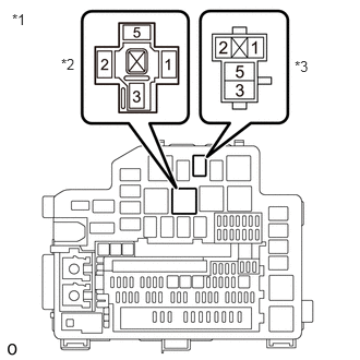
| *1 | No. 1 Engine Room Relay Block and No. 1 Junction Block Assembly |
| *2 | STARTER Relay |
| *3 | STARTER NO.2 Relay |
Remove the STARTER relay and STARTER NO.2 relay from the No. 1 engine room relay block and No. 1 junction block assembly.
Measure the voltage according to the value(s) in the table below.
- Standard Voltage:
Tester Connection Condition Specified Condition 5 (STARTER relay) - Body ground Always 9.5 to 14 V 5 (STARTER NO.2 relay) - Body ground Always 9.5 to 14 V
- Result:
Proceed to OK NG
OK
NG
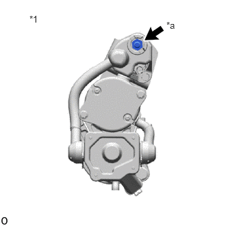
| *1 | Starter Assembly |
| *a | F3-1 (B) |
Measure the voltage according to the value(s) in the table below.
- Standard Voltage:
Tester Connection Condition Specified Condition F3-1 (B) - Body ground Always 9.5 to 14 V
- NOTICE:
-
Before performing this step, check that the starter assembly connector F3 is not disconnected or loose.
- Result:
Proceed to OK NG
OK
NG
Remove the STARTER relay and STARTER NO.2 relay from the No. 1 engine room relay block and No. 1 junction block assembly.
Disconnect the starter assembly connector.
Measure the resistance according to the value(s) in the table below.
- Standard Resistance:
Tester Connection Condition Specified Condition 3 (STARTER relay) - E44-1 (SL1) Always Below 1 Ω 3 (STARTER NO.2 relay) - E44-2 (SL2) Always Below 1 Ω
- Result:
Proceed to OK NG
OK
NG
Inspect the STARTER relay.
Inspect the STARTER NO.2 relay.
- Result:
Proceed to OK NG
OK
NG
Inspect the starter assembly.
- Result:
Proceed to OK NG
OK
NG