STOP AND START STOP AND START SYSTEM P085012 Park/Neutral Switch Circuit Short to Battery P085014 Park/Neutral Switch Circuit Short to Ground or Open
DESCRIPTION
- HINT:
-
This DTC is applicable to Automatic Transmission models only.
The engine stop and start ECU detects malfunctions by comparing the conditions of the shift position signal and NSW signal. If a malfunction is detected, the engine stop and start ECU blinks the stop and start cancel indicator, prohibits stop and start control and stores DTC P085012 or P085014.
| DTC No. | Detection Item | DTC Detection Condition | Trouble Area | Warning Indicate | Memory | Note |
|---|---|---|---|---|---|---|
| P085012 | Park/Neutral Switch Circuit Short to Battery | Both of the following conditions are met for 15 seconds or more (2 trip detection logic):
·
Ignition switch ON. ·
NSW signal is off with the shift lever in P or N. |
·
Wire harness or connector ·
Park/Neutral position switch assembly ·
ECM ·
Engine stop and start ECU |
Blinks | DTC stored | SAE Code: P0852 |
| P085014 | Park/Neutral Switch Circuit Short to Ground or Open | Both of the following conditions are met for 2 seconds or more (2 trip detection logic):
·
Ignition switch ON. ·
NSW signal is on with the shift lever not in P or N. |
·
Wire harness or connector ·
Park/Neutral position switch assembly ·
ECM ·
Engine stop and start ECU |
Blinks | DTC stored | SAE Code: P0851 |
WIRING DIAGRAM
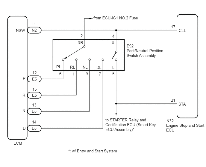
CAUTION / NOTICE / HINT
- NOTICE:
- ·
Before replacing the engine stop and start ECU, read the number of starter operations and write it into a new engine stop and start ECU.
·After replacing the engine stop and start ECU or air conditioning amplifier assembly, reset and perform learning of the air conditioning information in the engine stop and start ECU.
·After replacing the engine stop and start ECU or airbag sensor assembly, clear and calibrate the deceleration sensor zero point in the engine stop and start ECU.
·When the engine stop and start ECU or electromagnetic oil pump is replaced, check the electromagnetic oil pump.
·When the ECM is replaced on a vehicle with a non-specified battery, it is necessary to perform battery type switching.
·Before replacing the ECM, refer to Service Bulletin (for Immobiliser System).
·Inspect the fuses for circuits related to this system before performing the following procedure.
- HINT:
- ·
Using the GTS, read the freeze frame data before troubleshooting. System condition information is recorded as freeze frame data the moment a DTC is stored. This information can be useful when troubleshooting.
·DTCs for the stop and start system are not cleared even if the malfunction has been repaired. After repairing the malfunction, be sure to clear the DTCs.
PROCEDURE
Connect the GTS to the DLC3.
Turn the ignition switch to ON.
Turn the GTS on.
Enter the following menus: Powertrain / Engine / Data List / Shift SW Status (P, R, N, S, D Range).
- Powertrain > Engine > Data List
-
Tester Display Shift SW Status (P Range) Shift SW Status (R Range) Shift SW Status (N Range) Shift SW Status (S Range) Shift SW Status (D Range) - 50003 372 15,14,13,27,28
In accordance with the display on the GTS, read the Data List.
- Powertrain > Engine > Data List
-
Tester Display Measurement Item Range Normal Condition Shift SW Status (P Range) Park/Neutral position switch assembly status OFF or ON OFF: Shift lever not in P
ON: Shift lever in PShift SW Status (R Range) Park/Neutral position switch assembly status OFF or ON OFF: Shift lever not in R
ON: Shift lever in RShift SW Status (N Range) Park/Neutral position switch assembly status OFF or ON OFF: Shift lever not in N
ON: Shift lever in NShift SW Status (S Range) Park/Neutral position switch assembly status OFF or ON OFF: Shift lever not in S
ON: Shift lever in SShift SW Status (D Range) Park/Neutral position switch assembly status OFF or ON OFF: Shift lever not in D
ON: Shift lever in D
- Result:
Proceed to OK NG
OK
NG
Connect the GTS to the DLC3.
Turn the ignition switch to ON.
Turn the GTS on.
Enter the following menus: Powertrain / Engine / Data List / Neutral Position SW.
- Powertrain > Engine > Data List
-
Tester Display Neutral Position SW - 50003 372 20
In accordance with the display on the GTS, read the Data List.
- Powertrain > Engine
-
Tester Display Measurement Item Range Normal Condition Neutral Position SW Park/Neutral position switch assembly status OFF or ON OFF: Shift lever not in P or N
ON: Shift lever in P or N
- Result:
Proceed to OK NG
OK
NG
Inspect the park/neutral position switch assembly.
- Result:
Proceed to OK NG
OK
NG
Disconnect the engine stop and start ECU connector.
Disconnect the park/neutral position switch assembly connector.
Disconnect the ECM connector.
w/ Entry and Start System:
Disconnect the certification ECU (smart key ECU assembly) connector.
Remove the STARTER relay from the No. 1 engine room relay block and No. 1 junction block assembly.
Measure the resistance according to the value(s) in the table below.
- Standard Resistance:
Tester Connection Condition Specified Condition N32-21 (STA) - E92-5 (L) Always Below 1 Ω N32-17 (CLL) - E92-4 (B) Always Below 1 Ω N32-21 (STA) or E92-5 (L) - Body ground and other terminals Always 10 kΩ or higher N32-17 (CLL) or E92-4 (B) - Body ground and other terminals Always 10 kΩ or higher
- Result:
Proceed to OK NG
OK
NG
Inspect the park/neutral position switch assembly.
- Result:
Proceed to OK NG
OK
NG
Disconnect the ECM connector.
Disconnect the park/neutral position switch assembly connector.
Measure the resistance according to the value(s) in the table below.
- Standard Resistance:
Tester Connection Condition Specified Condition E5-12 (P) - E92-6 (PL) Always Below 1 Ω E5-15 (R) - E92-1 (RL) Always Below 1 Ω E5-13 (N) - E92-9 (NL) Always Below 1 Ω E5-14 (D) - E92-7 (DL) Always Below 1 Ω N2-11 (NSW) - E92-4 (B) Always Below 1 Ω
- Result:
Proceed to OK NG
OK
NG