PARK ASSIST / MONITORING PANORAMIC VIEW MONITOR SYSTEM C1622 Open or Short Circuit in Back Camera Signal
DESCRIPTION
This DTC is stored if the parking assist ECU judges as a result of its self check that the signals or signal lines between the parking assist ECU and the television camera assembly are not normal.
| DTC No. | Detection Item | DTC Detection Condition | Trouble Area |
|---|---|---|---|
| C1622 | Open or Short Circuit in Back Camera Signal | Open or short in the television camera signal circuit | ·
Harness or connector ·
Television camera assembly ·
Parking assist ECU |
WIRING DIAGRAM
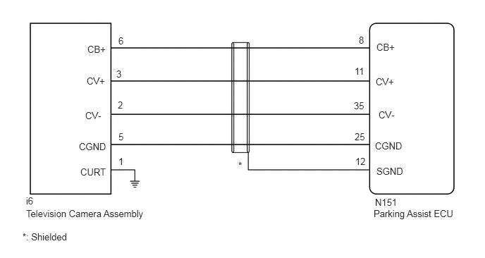
CAUTION / NOTICE / HINT
- NOTICE:
- ·
When the "!" mark is displayed on the multi-display after the cable is disconnected from the negative (-) battery terminal, correct the steering angle neutral point.
·Depending on the parts that are replaced or operations that are performed during vehicle inspection or maintenance, calibration of other systems as well as the panoramic view monitor system may be needed.
PROCEDURE
Disconnect the N151 parking assist ECU connector.
Disconnect the i6 television camera assembly connector.
Measure the resistance according to the value(s) in the table below.
- Standard Resistance:
Tester Connection Condition Specified Condition N151-8 (CB+) - i6-6 (CB+) Always Below 1 Ω N151-11 (CV+) - i6-3 (CV+) Always Below 1 Ω N151-35 (CV-) - i6-2 (CV-) Always Below 1 Ω N151-25 (CGND) - i6-5 (CGND) Always Below 1 Ω N151-12 (SGND) - Body ground Always Below 1 Ω i6-1 (CURT) - Body ground Always Below 1 Ω N151-8 (CB+) or i6-6 (CB+) - Body ground Always 10 kΩ or higher N151-11 (CV+) or i6-3 (CV+) - Body ground Always 10 kΩ or higher N151-35 (CV-) or i6-2 (CV-) - Body ground Always 10 kΩ or higher N151-25 (CGND) or i6-5 (CGND) - Body ground Always 10 kΩ or higher
- Result:
Proceed to OK NG
OK
NG
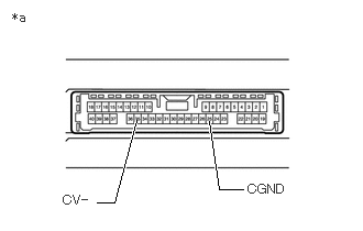
| *a | Component without harness connected
(Parking Assist ECU) |
Disconnect the N151 parking assist ECU connector.
Measure the resistance according to the value(s) in the table below.
- Standard Resistance:
Tester Connection Condition Specified Condition 35 (CV-) - Body ground Always Below 1 Ω 25 (CGND) - Body ground Always Below 1 Ω
- Result:
Proceed to OK NG
OK
NG
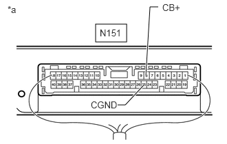
| *a | Component with harness connected
(Parking Assist ECU) |
Disconnect the television camera assembly.
Measure the resistance according to the value(s) in the table below.
- Standard Resistance:
Tester Connection Condition Specified Condition N151-25 (CGND) - Body ground Always Below 1 Ω
Measure the voltage according to the value(s) in the table below.
- Standard Voltage:
Tester Connection Switch Condition Specified Condition N151-8 (CB+) - N151-25 (CGND) Engine switch on (IG) 5.5 to 7.05 V N151-8 (CB+) - N151-25 (CGND) Engine switch off Below 1 V
- Result:
Proceed to OK NG
OK
NG
Using an oscilloscope, check the waveform of the television camera assembly.
- HINT:
-
A waterproof connector is used for the television camera assembly. Therefore, inspect the waveform at the parking assist ECU with the connector connected.
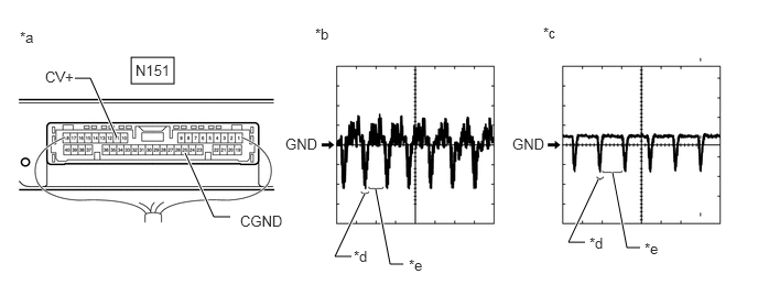
| *a | Component with harness connected
(Parking Assist ECU) |
*b | Waveform 1 (camera lens not covered, displaying an image) |
| *c | Waveform 2 (camera lens covered, blacking out the screen) | *d | Synchronization Signal |
| *e | Video Waveform | - | - |
- HINT:
- ·
The video waveform changes according to the image sent by the television camera assembly.
·The video waveform is constantly output when the engine switch is on (ACC).
| Item | Content |
|---|---|
| Terminal No. (Symbol) | N151-11 (CV+) - N151-25 (CGND) |
| Tool Setting | 200 mV/DIV., 50 μsec./DIV. |
| Condition | Engine switch on (IG), panoramic view monitor switch on |
- OK:
Waveform is similar to that shown in the illustration.
- Result:
Proceed to OK NG
OK
NG