☰ Toyota HiAce☰ فهرستAudio / Visual / Telematics › NAVIGATION / MULTI INFO DISPLAY › NAVIGATION SYSTEM
RM35X0E
_56
Audio / Visual / Telematics
_078379
NAVIGATION / MULTI INFO DISPLAY
_0380999
NAVIGATION SYSTEM
J
NAVIGATION / MULTI INFO DISPLAY NAVIGATION SYSTEM Sound Signal Circuit between Radio Receiver and Stereo Component Amplifier
DESCRIPTION
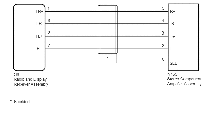
The radio and display receiver assembly sends a sound signal to the stereo component amplifier assembly via this circuit.
The sound signal that is sent is amplified by the stereo component amplifier assembly, and then is sent to the speakers.
If there is an open or short in this circuit, sound cannot be heard from the speakers even if the stereo component amplifier assembly or speakers are not malfunctioning.
WIRING DIAGRAM
5.583,2.396 6.74,2.854
1.156,0.458
10
false
N169
1.229,1.542 2.385,2
1.156,0.458
10
false
FL-
1.188,1.125 2.344,1.583
1.156,0.458
10
false
FL+
1.208,0.698 2.365,1.156
1.156,0.458
10
false
FR-
1.188,0.292 2.344,0.75
1.156,0.458
10
false
FR+
1.583,0.198 2.74,0.656
1.156,0.458
10
false
1
1.594,0.604 2.75,1.063
1.156,0.458
10
false
6
1.594,1.01 2.75,1.469
1.156,0.458
10
false
2
1.594,1.438 2.75,1.896
1.156,0.458
10
false
7
3.563,1.865 4.719,2.323
1.156,0.458
10
false
*
0.458,2.406 1.615,2.865
1.156,0.458
10
false
O8
0.458,2.563 1.677,2.99
1.219,0.427
10
false
Radio and Display Receiver Assembly
5.656,2.031 6.813,2.49
1.156,0.458
10
false
SLD
5.677,1.542 6.833,2
1.156,0.458
10
false
L-
5.677,1.135 6.833,1.594
1.156,0.458
10
false
L+
5.667,0.292 6.823,0.75
1.156,0.458
10
false
R+
5.708,0.698 6.865,1.156
1.156,0.458
10
false
R-
5.406,1.896 5.802,2.292
0.396,0.396
10
false
6
5.406,1.438 5.802,1.833
0.396,0.396
10
false
2
5.396,1.021 5.792,1.417
0.396,0.396
10
false
3
5.406,0.188 5.802,0.583
0.396,0.396
10
false
5
5.396,0.594 5.792,0.99
0.396,0.396
10
false
4
0.333,3.313 1.49,3.552
1.156,0.24
10
false
*: Shielded
5.573,2.552 6.792,2.979
1.219,0.427
10
false
Stereo Component Amplifier Assembly
PROCEDURE
1.CHECK HARNESS AND CONNECTOR (RADIO AND DISPLAY RECEIVER ASSEMBLY - STEREO COMPONENT AMPLIFIER ASSEMBLY)
a.
Disconnect the O8 radio and display receiver assembly connector.
b.
Disconnect the N169 stereo component amplifier assembly connector.
c.
Measure the resistance according to the value(s) in the table below.
- Standard Resistance:
Tester Connection Condition Specified Condition N169-5 (R+) - O8-1 (FR+) Always Below 1 Ω N169-4 (R-) - O8-6 (FR-) Always Below 1 Ω N169-3 (L+) - O8-2 (FL+) Always Below 1 Ω N169-2 (L-) - O8-7 (FL-) Always Below 1 Ω N169-6 (SLD) - Body ground Always 10 kΩ or higher N169-5 (R+) or O8-1 (FR+) - Body ground Always 10 kΩ or higher N169-4 (R-) or O8-6 (FR-) - Body ground Always 10 kΩ or higher N169-3 (L+) or O8-2 (FL+) - Body ground Always 10 kΩ or higher N169-2 (L-) or O8-7 (FL-) - Body ground Always 10 kΩ or higher
- Result:
Proceed to OK NG
OK
PROCEED TO NEXT SUSPECTED AREA SHOWN IN PROBLEM SYMPTOMS TABLE
NG
REPAIR OR REPLACE HARNESS OR CONNECTOR