HEATING / AIR CONDITIONING AIR CONDITIONING SYSTEM(for Manual Cooler System) B1423 Open in Pressure Sensor Circuit / Abnormal Refrigerant Pressure
DESCRIPTION
This DTC is stored if refrigerant pressure on the high pressure side is extremely low (176 kPa (1.8 kgf/cm2, 26 psi) or less) or extremely high (3025 kPa (30.8 kgf/cm2, 439 psi) or more). The air conditioner pressure sensor, which is installed to the high pressure side pipe to detect refrigerant pressure, sends a refrigerant pressure signal to the air conditioning amplifier assembly. The air conditioning amplifier assembly converts this signal to a pressure value according to the sensor characteristics and uses it to control the compressor.
| DTC No. | Detection Item | DTC Detection Condition | Trouble Area | Memory |
|---|---|---|---|---|
| B1423 | Pressure Sensor Circuit | ·
Diagnosis condition: Ignition switch ON ·
Malfunction Status: Refrigerant pressure signal malfunction ·
Detection time: Continuously for 4 seconds or more (Present malfunction) |
·
Air conditioner pressure sensor ·
Harness or connector ·
Air conditioning system (leaks, blocked) ·
Cooler expansion valve (blocked, stuck) ·
Cooler condenser assembly (blocked, deterioration of cooling capacity due to dirt) ·
Cooler dryer (moisture in the refrigerant cycle cannot be absorbed) ·
Air conditioning amplifier assembly ·
Cooling fan system (cooler condenser assembly cannot be cooled down) ·
Refrigerant pressure (overcharged, lack) |
- |
WIRING DIAGRAM
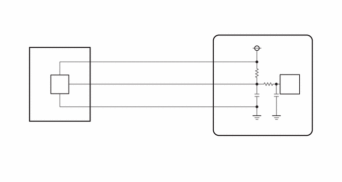
PROCEDURE
Check for DTCs.
- Body Electrical > Air Conditioner > Trouble Codes
- 50001 121
- Result:
Result Proceed to DTC B1423 and B14B8 are output A DTC B1423 is output B
A
B
Connect the GTS to the DLC3.
Turn the ignition switch to ON.
Turn the GTS on.
Enter the following menus: Body Electrical / Air Conditioner / Data List.
Read the Data List according to the display on the GTS.
- Body Electrical > Air Conditioner > Data List
-
Tester Display Measurement Item Range Normal Condition Diagnostic Note Regulator Pressure Sensor Air conditioner pressure sensor Min.: -0.4566 MPaG (gauge)
Max.: 3.2943 MPaG (gauge)Actual refrigerant pressure displayed ·Refrigerant line (gas leak etc.)
·Air conditioner pressure sensor system malfunction
- Body Electrical > Air Conditioner > Data List
-
Tester Display Regulator Pressure Sensor - 50003 121 51
Read the manifold gauge pressure when the following conditions are met.
Prepare the vehicle according to the table below.
| Item | Condition |
|---|---|
| Vehicle Condition | Engine running |
| Doors | Fully closed (windows also fully closed) |
| Temperature Switch | On |
| Recirculation/fresh Control Switch | Recirculation |
| Set Temperature | MAX COLD |
| Blower Speed | HI |
| Air Conditioning Air Inlet Temperature | 25 to 35°C (77 to 95°F) |
Compare the values displayed in the Data List and on the manifold gauge.
- Result:
Result Proceed to Data List value and manifold gauge set value do not match and Data List value: 176 kPa (1.8 kgf/cm2) or less A Data List value and manifold gauge set value do not match and Data List value: 3025 kPa (30.9 kgf/cm2) or less B Data List value matches manifold gauge set value C
A
B
C
Connect the GTS to the DLC3.
Turn the ignition switch to ON.
Turn the GTS on.
Enter the following menus: Body Electrical / Air Conditioner / Data List.
Read the Data List according to the display on the GTS.
- Body Electrical > Air Conditioner > Data List
-
Tester Display Measurement Item Range Normal Condition Diagnostic Note Regulator Pressure Sensor Air conditioner pressure sensor Min.: -0.4566 MPaG (gauge)
Max.: 3.2943 MPaG (gauge)Actual refrigerant pressure displayed ·Refrigerant line (gas leak etc.)
·Air conditioner pressure sensor system malfunction
- Body Electrical > Air Conditioner > Data List
-
Tester Display Regulator Pressure Sensor - 50003 121 51
- OK:
Disconnecting the A37 connector of the air conditioner pressure sensor causes the Data List value to change.
- Result:
Result Proceed to Regulator pressure sensor value changes A Regulator pressure sensor value does not change B
A
B
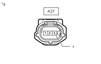
| *a | Front view of wire harness connector
(to Air Conditioner Pressure Sensor) |
Disconnect the air conditioner pressure sensor connector.
Measure the voltage according to the value(s) in the table below.
- Standard Voltage:
Tester Connection Switch Condition Specified Condition A37-3 (+) - Body ground Ignition switch ON 4.75 to 5.25 V
- Result:
Proceed to OK NG
OK
NG
Disconnect the N41 air conditioning amplifier assembly connector.
Disconnect the A37 air conditioner pressure sensor connector.
Measure the resistance according to the value(s) in the table below.
- Standard Resistance:
Tester Connection Condition Specified Condition N41-11 (S5-3) - A37-3 (+) Always Below 1 Ω
- Result:
Proceed to OK NG
OK
NG
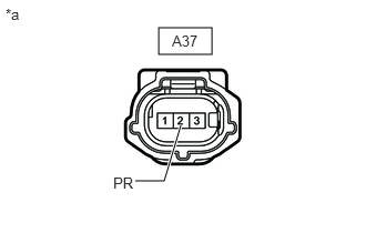
| *a | Front view of wire harness connector
(to Air Conditioner Pressure Sensor) |
Disconnect the air conditioner pressure sensor connector.
Measure the voltage according to the value(s) in the table below.
- Standard Voltage:
Tester Connection Switch Condition Specified Condition A37-2 (PR) - Body ground Ignition switch ON 3.0 to 5.25 V
- Result:
Proceed to OK NG
OK
NG
Disconnect the N41 air conditioning amplifier assembly connector.
Disconnect the A37 air conditioner pressure sensor connector.
Measure the resistance according to the value(s) in the table below.
- Standard Resistance:
Tester Connection Condition Specified Condition N41-6 (PRE) or A37-2 (PR) - Other terminals and body ground Always 10 kΩ or higher
- Result:
Proceed to OK NG
OK
NG

| *a | Front view of wire harness connector
(to Air Conditioner Pressure Sensor) |
Disconnect the air conditioner pressure sensor connector.
Measure the resistance according to the value(s) in the table below.
- Standard Resistance:
Tester Connection Condition Specified Condition A37-1 (-) - Body ground Always Below 1 Ω
- Result:
Proceed to OK NG
OK
NG
| *a | Front view of wire harness connector
(to Air Conditioner Pressure Sensor) |
Disconnect the air conditioner pressure sensor connector.
Measure the voltage according to the value(s) in the table below.
- Standard Voltage:
Tester Connection Switch Condition Specified Condition A37-2 (PR) - Body ground Ignition switch ON 3.0 to 5.25 V
- Result:
Result Proceed to 5.25 V or higher A 3.0 to 5.25 V B Below 3.0 V C
A
B
C
Disconnect the N41 air conditioning amplifier assembly connector.
Disconnect the A37 air conditioner pressure sensor connector.
Measure the resistance according to the value(s) in the table below.
- Standard Resistance:
Tester Connection Condition Specified Condition N41-6 (PRE) or A37-2 (PR) - Other terminals and body ground Always 10 kΩ or higher
- Result:
Proceed to OK NG
OK
NG
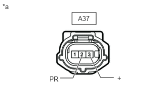
| *a | Front view of wire harness connector
(to Air Conditioner Pressure Sensor) |
Disconnect the air conditioner pressure sensor connector.
Measure the resistance according to the value(s) in the table below.
- Standard Resistance:
Tester Connection Condition Specified Condition A37-2 (PR) - A37-3 (+) Ignition switch off 180 to 220 kΩ
- HINT:
-
After turning the ignition switch off, wait at least 30 seconds before performing the measurement.
- Result:
Proceed to OK NG
OK
NG
Disconnect the N41 air conditioning amplifier assembly connector.
Disconnect the A37 air conditioner pressure sensor connector.
Measure the resistance according to the value(s) in the table below.
- Standard Resistance:
Tester Connection Condition Specified Condition N41-6 (PRE) or A37-2 (PR) - Other terminals and body ground Always 10 kΩ or higher N41-11 (S5-3) or A37-3 (+) - Other terminals and body ground Always 10 kΩ or higher
- Result:
Proceed to OK NG
OK
NG
Disconnect the N41 air conditioning amplifier assembly connector.
Disconnect the A37 air conditioner pressure sensor connector.
Measure the resistance according to the value(s) in the table below.
- Standard Resistance:
Tester Connection Condition Specified Condition N41-6 (PRE) - A37-2 (PR) Always Below 1 Ω
- Result:
Proceed to OK NG
OK
NG
Disconnect the N41 air conditioning amplifier assembly connector.
Disconnect the A37 air conditioner pressure sensor connector.
Measure the resistance according to the value(s) in the table below.
- Standard Resistance:
Tester Connection Condition Specified Condition N41-15 (SG-4) - A37-1 (-) Always Below 1 Ω N41-15 (SG-4) or A37-1 (-) - Other terminals and body ground Always 10 kΩ or higher
- Result:
Proceed to OK NG
OK
NG