AC60E AUTOMATIC TRANSMISSION / TRANSAXLE AUTOMATIC TRANSMISSION SYSTEM(for 7GR-FKS) P072012 Output Speed Sensor Circuit Short to Battery P072014 Output Speed Sensor Circuit Short to Ground or Open P072031 Output Speed Sensor No Signal
DESCRIPTION
This sensor detects the rotation speed of the transmission output shaft and sends signals to the ECM. By comparing the input turbine speed signal (NT) with the output shaft speed sensor signal (SP2), the ECM detects the shift timing of the gears and appropriately controls the engine torque and hydraulic pressure according to various conditions. As a result, the gears shift smoothly.
| DTC No. | Detection Item | DTC Detection Condition | Trouble Area | MIL | Memory | Note |
|---|---|---|---|---|---|---|
| P072012 | Output Speed Sensor Circuit Short to Battery | When the transmission revolution sensor (SP2) input voltage is higher than 1.8 V for 4.5 seconds or more (1 trip detection logic). | ·
Harness or connector ·
Transmission revolution sensor (SP2) ·
ECM |
Comes on | DTC stored | SAE: P077D |
| P072014 | Output Speed Sensor Circuit Short to Ground or Open | When the transmission revolution sensor (SP2) input voltage is below 0.2 V for 4.5 seconds or more (1 trip detection logic). | ·
Harness or connector ·
Transmission revolution sensor (SP2) ·
ECM |
Comes on | DTC stored | SAE: P077C |
| P072031 | Output Speed Sensor No Signal | All conditions are met for 5 seconds or more (1 trip detection logic):
·
Park/neutral position switch D input signal is ON. ·
The vehicle speed is 9 km/h (5.6 mph) or more. ·
Either condition is met. -
Gear position is 1st: Transmission revolution sensor (NT) value is 1310 rpm or more. -
Gear position is 2nd, 3rd, 4th, 5th or 6th: Transmission revolution sensor (NT) value is 760 rpm or more. ·
No signal from transmission revolution sensor (SP2) is input to the ECM. |
·
Harness or connector ·
Transmission revolution sensor (SP2) ·
ECM |
Comes on | DTC stored | SAE: P0722 |
| Vehicle Condition | |||
|---|---|---|---|
| Pattern 1 | Pattern 2 | ||
| Diagnostic Condition | Park/neutral position switch D input signal is ON. | ○ | ○ |
| The vehicle speed is 9 km/h (5.6 mph) or more. | ○ | ○ | |
| Gear position is 1st:
Transmission revolution sensor (NT) value is 1310 rpm or more. |
○ | - | |
| Gear position is 2nd, 3rd, 4th, 5th or 6th:
Transmission revolution sensor (NT) value is 760 rpm or more. |
- | ○ | |
| Malfunction Condition | No signal from transmission revolution sensor (SP2) is input to the ECM. | ○ | ○ |
| Duration | 5 seconds or more | 5 seconds or more | |
| Detection Logic | 1 trip detection logic | 1 trip detection logic | |
- HINT:
-
DTC P072031 is stored when either of the above detection patterns are met.
MONITOR DESCRIPTION
The transmission revolution sensor (SP2) detects the transmission output shaft speed. The ECM calculates gear shifts comparing the transmission revolution sensor (NT) with the transmission revolution sensor (SP2).
If the ECM detects no signal from the transmission revolution sensor (SP2) even while the vehicle is moving, it will conclude that there is a malfunction in the transmission revolution sensor (SP2). The ECM will illuminate the MIL and store the DTC.
CONFIRMATION DRIVING PATTERN
- CAUTION:
-
When performing the confirmation driving pattern, obey all speed limits and traffic laws.
- HINT:
-
After repair has been completed, clear the DTCs and then check that the vehicle has returned to normal by performing the following All Readiness check procedure.
Connect the GTS to the DLC3.
Turn the ignition switch to ON and turn the GTS on.
Clear the DTCs (even if no DTCs are stored, perform the clear DTC procedure).
Turn the ignition switch off and wait for at least 30 seconds.
Turn the ignition switch to ON and turn the GTS on.
Perform the D Position Shift Test inspection in Road Test.
Enter the following menus: Powertrain / Transmission / Utility / All Readiness.
Input the DTC: P072012, P072014 or P072031.
Check the DTC judgment result.
| GTS Display | Description |
|---|---|
| NORMAL | ·
DTC judgment completed ·
System normal |
| ABNORMAL | ·
DTC judgment completed ·
System abnormal |
| INCOMPLETE | ·
DTC judgment not completed ·
Perform driving pattern after confirming DTC enabling conditions |
| N/A | ·
Unable to perform DTC judgment ·
Number of DTCs which do not fulfill DTC preconditions has reached ECU memory limit |
- HINT:
- ·
If the judgment result shows NORMAL, the system is normal.
·If the judgment result shows ABNORMAL, the system has a malfunction.
·If the judgment result shows INCOMPLETE or N/A, perform the Confirmation Driving Pattern and check the DTC judgment result again.
WIRING DIAGRAM
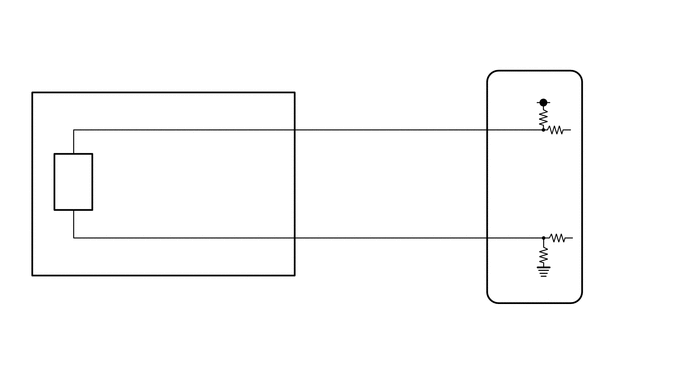
CAUTION / NOTICE / HINT
- NOTICE:
-
Perform registration and/or initialization when parts related to the automatic transmission are replaced.
DATA LIST
- HINT:
-
Using the GTS to read the Data List allows the values or states of switches, sensors, actuators and other items to be read without removing any parts. This non-intrusive inspection can be very useful because intermittent conditions or signals may be discovered before parts or wiring is disturbed. Reading the Data List information early in troubleshooting is one way to save diagnostic time.
- NOTICE:
-
In the table below, the values listed under "Normal Condition" are reference values. Do not depend solely on these reference values when deciding whether a part is faulty or not.
Warm up the engine.
Turn the ignition switch off.
Connect the GTS to the DLC3.
Turn the ignition switch to ON.
Turn the GTS on.
Enter the following menus: Powertrain / Transmission / Data List / Speed (SP2).
Read the Data List according to the display on the GTS.
- Powertrain > Transmission > Data List
-
Tester Display Measurement Item Range Normal Condition Diagnostic Note Speed (SP2) Output shaft speed Min.: 0 km/h (0 mph)
Max.: 255 km/h (158 mph)0 km/h (0 mph): Vehicle stopped (equal to vehicle speed) -
- Powertrain > Transmission > Data List
-
Tester Display Speed (SP2) - 50003 373 362
- HINT:
- ·
Speed (SP2) is always 0 while driving: Open or short in the sensor or circuit.
·Speed (SP2) value displayed on the GTS is much lower than the actual vehicle speed: Sensor trouble, improper installation, or intermittent connection trouble of the circuit.
PROCEDURE
Connect the GTS to the DLC3.
Turn the ignition switch to ON.
Turn the GTS on.
Enter the following menus: Powertrain / Transmission / Data List / Speed (SP2), SP2 Sensor Voltage.
Read the Data List according to the display on the GTS.
- Powertrain > Transmission > Data List
-
Tester Display Measurement Item Range Normal Condition Diagnostic Note Speed (SP2) Output shaft speed Min.: 0 km/h (0 mph)
Max.: 255 km/h (158 mph)0 km/h (0 mph): Vehicle stopped
(Output shaft speed is equal to vehicle speed)- SP2 Sensor Voltage Transmission revolution sensor (SP2) sensor voltage Min.: 0.000 V
Max.: 4.999 V0.2 to 1.8 V: Engine idling -
- Powertrain > Transmission > Data List
-
Tester Display Speed (SP2) SP2 Sensor Voltage - 50003 373 362,391
- Result:
Result Proceed to Data display is not within Normal Condition range A Data display is within Normal Condition range B
A
B
Remove the transmission revolution sensor (SP2).
Connect the battery to the sensor as shown in the illustration.
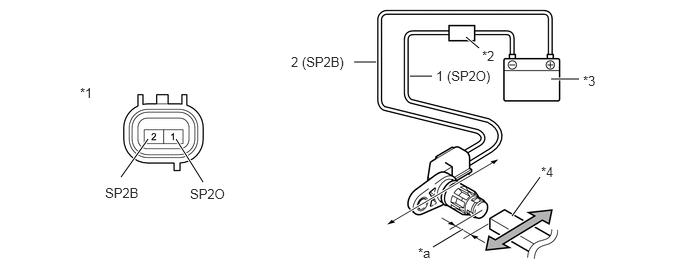
| *1 | Transmission Revolution Sensor (SP2) | *2 | Ammeter |
| *3 | Battery | *4 | Magnet |
| *a | 5 mm (0.197 in.) or less | - | - |
Wave a magnetic object left and right in front of the transmission revolution sensor (SP2) tip (5 mm (0.197 in.) or less) to change the high/low signals while measuring the current.
- NOTICE:
-
Make sure to wave the magnetic object during the inspection. The current will not change without waving the magnetic object as indicated by the arrow in the illustration.
Measure the current according to the value(s) in the table below.
- Standard Current:
Tester Connection Condition Specified Condition 1 (SP2O) - 2 (SP2B) Low signal 4 to 8 mA 1 (SP2O) - 2 (SP2B) High signal 12 to 16 mA
- Result:
Proceed to OK NG
OK
NG
Disconnect the transmission revolution sensor (SP2) connector.
Disconnect the ECM connector.
Measure the resistance according to the value(s) in the table below.
- Standard Resistance:
Tester Connection Condition Specified Condition E39-2 (SP2B) - E4-26 (SP2B) Always Below 1 Ω E39-1 (SP2O) - E4-33 (SP2O) Always Below 1 Ω E39-2 (SP2B) - Body ground Always 10 kΩ or higher E39-1 (SP2O) - Body ground Always 10 kΩ or higher
- Result:
Proceed to OK NG
OK
NG