CRUISE CONTROL CAMERA HEATER INSTALLATION
PROCEDURE

 86401
1.INSTALL FORWARD RECOGNITION WITH HEATER HOOD SUB-ASSEMBLY
86401
1.INSTALL FORWARD RECOGNITION WITH HEATER HOOD SUB-ASSEMBLY
- NOTICE:
-
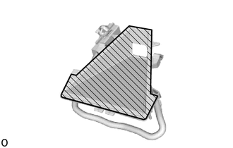 0,0 0,0 false
Inner Surface of Forward Recognition with Heater Hood Sub-assembly
- ·
Do not touch the inner surface of the forward recognition with heater hood sub-assembly.
·Do not apply force to the heating element of the forward recognition with heater hood sub-assembly or an open circuit may result.
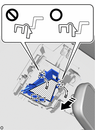

|
Install in this Direction (1) |

|
Install in this Direction (2) |
|
|
Heater Area |
Insert the forward recognition with heater hood sub-assembly in the direction indicated by the arrow (1) as shown in the illustration to attach the guide.
Attach the claw in the direction indicated by the arrow (2) as shown in the illustration.
- NOTICE:
- ·
Make sure that the 2 claws are attached as shown in the illustration. Failure to do so may result in the malfunction of systems that use the forward recognition camera.
·Do not apply force to the heating element of the forward recognition with heater hood sub-assembly or an open circuit may result.
- HINT:
-
Check the locking sound of the clip when attaching it.
Install the wire harness to the guide in the order shown in the illustration.

| *a | Wire Harness | *b | Connector Clamp |
Attach the connector clamp to install the forward recognition with heater hood sub-assembly.
Connect the connector.
8646C
2.INSTALL FORWARD RECOGNITION CAMERA