BRAKE CONTROL / DYNAMIC CONTROL SYSTEMS ELECTRONICALLY CONTROLLED BRAKE SYSTEM(w/o VSC OFF Switch) P057113 Brake Switch "A" Circuit Open
DESCRIPTION
The skid control ECU (brake actuator assembly) receives stop light switch assembly signals and uses them to determine whether or not the brakes are applied.
The skid control ECU (brake actuator assembly) has a detection circuit that it uses to detect an open in the stop light input line.
If the skid control ECU (brake actuator assembly) detects an open in this circuit, it will store this DTC.
| DTC No. | Detection Item | DTC Detection Condition | Trouble Area |
|---|---|---|---|
| P057113 | Brake Switch "A" Circuit Open | An open in the stop light switch assembly input line continues for 3 seconds or more. | ·
Stop light switch assembly ·
Wire harness or connector ·
Skid control ECU (brake actuator assembly) |
WIRING DIAGRAM

CAUTION / NOTICE / HINT
- NOTICE:
-
After replacing the skid control ECU (brake actuator assembly), perform store system information memorization.
PROCEDURE
Turn the ignition switch off.
Remove the stop light switch assembly.
Inspect the stop light switch assembly.
- OK:
The stop light switch assembly is normal.
- Result:
Result OK NG
OK
NG
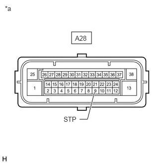
| *a | Front view of wire harness connector
(to Skid Control ECU (Brake Actuator Assembly)) |
Make sure that there is no looseness at the locking part and the connecting part of the connector.
- OK:
The connector is securely connected.
Reconnect the stop light switch assembly.
Disconnect the A28 skid control ECU (brake actuator assembly) connector.
Check both the connector case and the terminals for deformation and corrosion.
- OK:
No deformation or corrosion.
Measure the voltage according to the value(s) in the table below.
- Standard Voltage:
Tester Connection Condition Specified Condition A28-9 (STP) - Body ground Brake pedal depressed 11 to 14 V
- Result:
Proceed to OK NG
OK
NG