7GR-FKS ENGINE CONTROL MASS AIR FLOW METER ON-VEHICLE INSPECTION
PROCEDURE

 22204
1.INSPECT INTAKE MASS AIR FLOW METER SUB-ASSEMBLY
22204
1.INSPECT INTAKE MASS AIR FLOW METER SUB-ASSEMBLY
- HINT:
-
Perform "Inspection After Repair" after replacing the intake mass air flow meter sub-assembly.
Read the value of Data List item "Mass Air Flow Sensor" using the GTS.
- NOTICE:
-
Perform the inspection of the intake mass air flow meter sub-assembly while it is installed to the air cleaner cap sub-assembly (installed to the vehicle).
Check and ensure the following conditions:
Turn off all electrical loads, such as the air conditioning, etc.
Check that the coolant temperature is 75°C (167°F) or more.
Put the shift lever in the N position.
Connect the GTS to the DLC3.
Start the engine.
Turn the GTS on.
According to the display on the GTS, read the Data List when the engine is running.
- Powertrain > Engine > Data List
-
Tester Display Mass Air Flow Sensor - 50003 372 215
- Standard Condition:
GTS Display Condition Specified Condition Mass Air Flow Sensor Idling (engine warmed up) 2.6 to 3.7 gm/sec 2000 rpm (without load) 5.4 to 10.0 gm/sec 3000 rpm (without load) 10.6 to 15.8 gm/sec
If the result is not as specified, clean (air blow) the intake mass air flow meter sub-assembly.
After cleaning (air blowing) the intake mass air flow meter sub-assembly, perform an on-vehicle inspection of the intake mass air flow meter sub-assembly again and replace the intake mass air flow meter sub-assembly if the result is not as specified.
If the result is within the specified range, check the intake air temperature sensor (thermistor) resistance.
22204
2.CLEAN INTAKE MASS AIR FLOW METER SUB-ASSEMBLY
- NOTICE:
-
If the mass air flow meter sub-assembly is removed and installed 10 times or more, the thread of the hole of the mass air flow meter sub-assembly may be damaged. Therefore, do not loosen the screws of the mass air flow meter sub-assembly.
Remove the air cleaner cap sub-assembly.
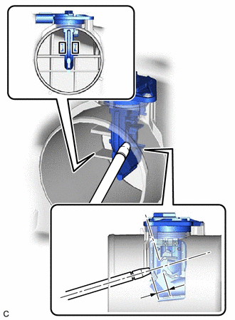
| *1 | Intake Mass Air Flow Meter Sub-assembly |
| *a | Air Blow Gun |
| *b | 10 mm (0.394 in.) |
| *c | Airflow Hole |
Clean the intake mass air flow meter sub-assembly.
- NOTICE:
- ·
Do not contact the intake mass air flow meter sub-assembly with the nozzle of the air blow gun.
·Do not insert the nozzle of the air blow gun into the airflow hole.
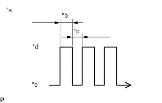
| *a | Air Blow Duration |
| *b | 3 to 6 Seconds |
| *c | 1 Second |
| *d | Air Blowing |
| *e | Air Stopped |
Using an air blow gun, clean the hole of the intake mass air flow meter sub-assembly by applying approximately 10 intermittent bursts of air to the airflow hole at a pressure of approximately 392 to 981 kPa (4.0 to 10.0 kgf/cm2, 57 to 142 psi).
- HINT:
-
Apply 5 intermittent bursts of air to the airflow hole at 2 locations.
Install the air cleaner cap sub-assembly.
3.PERFORM INITIALIZATION
Perform "Inspection After Repair" after replacing the intake mass air flow meter sub-assembly.