7GR-FKS ENGINE CONTROL MASS AIR FLOW METER INSPECTION
PROCEDURE

 22204
1.INSPECT INTAKE MASS AIR FLOW METER SUB-ASSEMBLY
22204
1.INSPECT INTAKE MASS AIR FLOW METER SUB-ASSEMBLY
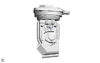
| *a | Intake Air Temperature Sensor (Thermistor) |
Perform a visual check for any foreign matter on the intake air temperature sensor (thermistor) of the intake mass air flow meter sub-assembly shown in the illustration.
- OK:
There is no foreign matter.
If the result is not as specified, clean the intake air temperature sensor (thermistor).
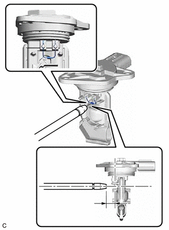
| *a | Air Blow Gun |
| *b | 10 mm (0.394 in.) |
| *c | Intake Air Temperature Sensor (Thermistor) |
Clean the intake air temperature sensor (thermistor).
- NOTICE:
- ·
Do not contact the intake mass air flow meter sub-assembly with the nozzle of the air blow gun.
·Do not insert the nozzle of the air blow gun into the intake air temperature sensor (thermistor) area.
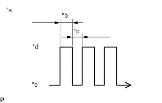
| *a | Air Blow Duration |
| *b | 3 to 6 Seconds |
| *c | 1 Second |
| *d | Air Blowing |
| *e | Air Stopped |
Using an air blow gun, clean the intake air temperature sensor (thermistor) area of the intake mass air flow meter sub-assembly by applying approximately 10 intermittent bursts of air to the intake air temperature sensor (thermistor) area at a pressure of approximately 392 to 981 kPa (4.0 to 10.0 kgf/cm2, 57 to 142 psi).
- HINT:
-
After performing cleaning, check the intake air temperature sensor (thermistor) resistance.
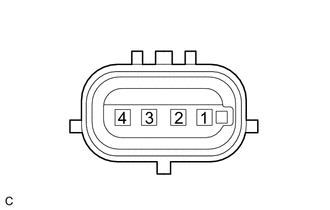
| *a | Component without harness connected
(Intake Mass Air Flow Meter Sub-assembly) |
Check the intake air temperature sensor (thermistor) resistance.
Measure the resistance according to the value(s) in the table below.
- Standard Resistance:
Tester Connection Condition Specified Condition 4 (THA) - 2 (E2G) Always 0.47 to 19.3 kΩ
If the result is not as specified, replace the intake mass air flow meter sub-assembly.