RM35X0E
_58
Vehicle Interior
_078337
METER / GAUGE / DISPLAY
_0379907
METER / GAUGE SYSTEM
J
METER / GAUGE / DISPLAY METER / GAUGE SYSTEM Fuel Filter Level Warning Switch Circuit
DESCRIPTION
The combination meter assembly and fuel filter assembly are connected via direct line. The combination meter assembly determines the fuel filter level based on the diesel fuel filter assembly signal.
WIRING DIAGRAM
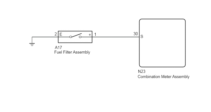
1.844,1.688 3.865,2.094
2.021,0.406
10
false
Fuel Filter Assembly
1.865,1.531 2.167,1.708
0.302,0.177
10
false
A17
2.021,1.083 2.188,1.24
0.167,0.156
10
false
E
3.01,1.094 3.177,1.25
0.167,0.156
10
false
+
3.198,1.083 3.365,1.24
0.167,0.156
10
false
1
1.854,1.073 2.021,1.229
0.167,0.156
10
false
2
4.531,1.063 4.823,1.24
0.292,0.177
10
false
30
4.771,1.156 5.188,1.323
0.417,0.167
10
false
S
4.688,2.344 5.385,2.521
0.698,0.177
10
false
N23
4.677,2.521 6.542,2.771
1.865,0.25
10
false
Combination Meter Assembly
CAUTION / NOTICE / HINT
- NOTICE:
-
When replacing the combination meter assembly, always replace it with a new one. If a combination meter assembly which was installed to another vehicle is used, the information stored in it will not match the information from the vehicle and a DTC may be stored.
PROCEDURE
1.INSPECT DIESEL FUEL FILTER ASSEMBLY
a.
Remove the diesel fuel filter assembly.
b.
Inspect the diesel fuel filter assembly.
- Result:
Proceed to OK NG
OK
2.CHECK HARNESS AND CONNECTOR (DIESEL FUEL FILTER ASSEMBLY - COMBINATION METER ASSEMBLY AND BODY GROUND)
NG
REPLACE DIESEL FUEL FILTER ASSEMBLY
2.CHECK HARNESS AND CONNECTOR (DIESEL FUEL FILTER ASSEMBLY - COMBINATION METER ASSEMBLY AND BODY GROUND)
a.
Disconnect the A17 diesel fuel filter assembly connector.
b.
Disconnect the N23 combination meter assembly connector.
c.
Measure the resistance according to the value(s) in the table below.
- Standard Resistance:
Tester Connection Condition Specified Condition N23-30 (S) - A17-1 (+) Always Below 1 Ω A17-2 (E) - body ground Always Below 1 Ω N23-30 (S) or A17-1 (+) - Other terminals and body ground Always 10 kΩ or higher
- Result:
Proceed to OK NG
OK
REPLACE COMBINATION METER ASSEMBLY
NG
REPAIR OR REPLACE HARNESS OR CONNECTOR