RM35X0E
_58
Vehicle Interior
_078337
METER / GAUGE / DISPLAY
_0379907
METER / GAUGE SYSTEM
J
METER / GAUGE / DISPLAY METER / GAUGE SYSTEM Back-up Light Switch Circuit
DESCRIPTION
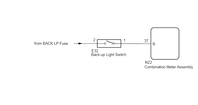
The combination meter assembly and back-up light switch are connected via direct line. The combination meter assembly determines the back-up light switch signal.
WIRING DIAGRAM
3.302,1.896 5.323,2.302
2.021,0.406
10
false
Back-up Light Switch
3.313,1.76 3.615,1.938
0.302,0.177
10
false
E32
4.469,1.375 4.635,1.531
0.167,0.156
10
false
1
3.375,1.365 3.542,1.521
0.167,0.156
10
false
2
5.219,1.396 5.51,1.573
0.292,0.177
10
false
37
5.521,1.51 5.938,1.677
0.417,0.167
10
false
R
5.25,2.177 5.948,2.354
0.698,0.177
10
false
N22
5.229,2.344 7.156,2.5
1.927,0.156
10
false
Combination Meter Assembly
1.24,1.49 3.26,1.896
2.021,0.406
10
false
from BACK LP Fuse
CAUTION / NOTICE / HINT
- NOTICE:
-
When replacing the combination meter assembly, always replace it with a new one. If a combination meter assembly which was installed to another vehicle is used, the information stored in it will not match the information from the vehicle and a DTC may be stored.
PROCEDURE
1.INSPECT BACK-UP LIGHT SWITCH
a.
Remove the back-up light switch.
b.
Inspect the back-up light switch.
- Result:
Proceed to OK NG
OK
2.CHECK HARNESS AND CONNECTOR (BACK-UP LIGHT SWITCH - COMBINATION METER ASSEMBLY AND BATTERY)
NG
REPLACE BACK-UP LIGHT SWITCH
2.CHECK HARNESS AND CONNECTOR (BACK-UP LIGHT SWITCH - COMBINATION METER ASSEMBLY AND BATTERY)
a.
Disconnect the N22 combination meter assembly connector.
b.
Disconnect the E32 back-up light switch connector.
c.
Measure the resistance according to the value(s) in the table below.
- Standard Resistance:
Tester Connection Condition Specified Condition N22-37 (R) - E32-1 Always Below 1 Ω N22-37 (R) or E32-1 - Other terminals and body ground Always 10 kΩ or higher
d.
Measure the voltage according to the value(s) in the table below.
- Standard Voltage:
Tester Connection Switch Condition Specified Condition E32-2 - Body ground Ignition switch ON 11 to 14 V
- Result:
Proceed to OK NG
OK
REPLACE COMBINATION METER ASSEMBLY
NG
REPAIR OR REPLACE HARNESS OR CONNECTOR