PARKING BRAKE PARKING BRAKE ASSEMBLY(for Rear Disc Brake) REASSEMBLY
CAUTION / NOTICE / HINT
- HINT:
- ·
Use the same procedure for the RH and LH sides.
·The procedure listed below is for the LH side.
PROCEDURE

 1.APPLY HIGH-TEMPERATURE GREASE
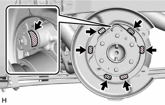

|
High-temperature grease |
Apply a light coat of high-temperature grease to the areas of the backing plate which make contact with the shoe as shown in the illustration.
2.INSTALL PARKING BRAKE SHOE HOLD DOWN SPRING PIN
for Front Side:
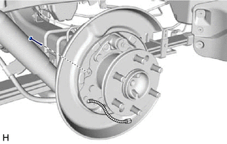
Install the parking brake shoe hold down spring pin.
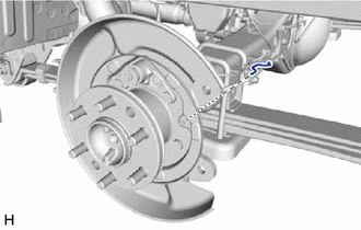
for Rear Side:
Install the parking brake shoe hold down spring pin.
3.INSTALL PARKING BRAKE SHOE LEVER LH
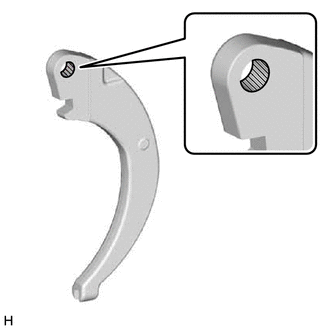
|
|
High-temperature grease |
Apply a light coat of high-temperature grease to the areas of the parking brake shoe lever LH which make contact with the No. 1 parking brake shoe assembly LH.
Temporarily install the parking brake shoe lever LH and shim to the No. 2 parking brake shoe assembly LH with the C-washer.

Using a feeler gauge, measure the clearance between the No. 2 parking brake shoe assembly LH and parking brake shoe lever LH.
- Standard clearance:
Less than 0.25 mm (0.00984 in.)
If the clearance is not within the specification, replace the shim with one of a different thickness so that the clearance is within the specification.
- Standard Shim:
Thickness Thickness 0.3 mm (0.0118 in.) 0.6 mm (0.0236 in.) 0.4 mm (0.0157 in.) 0.9 mm (0.0354 in.) 0.5 mm (0.0197 in.) -
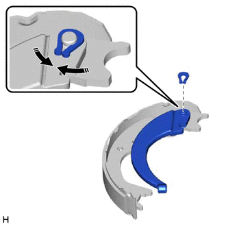

|
Install in this Direction |
Install the parking brake shoe lever LH and shim to the No. 2 parking brake shoe assembly LH with a new C-washer as shown in the illustration.
Using a feeler gauge, measure the clearance between the No. 2 parking brake shoe assembly LH and parking brake shoe lever LH.
- Standard clearance:
Less than 0.25 mm (0.00984 in.)
If the clearance is not within the specification, replace the shim with one of a different thickness so that the clearance is within the specification.
- Standard Shim:
Thickness Thickness 0.3 mm (0.0118 in.) 0.6 mm (0.0236 in.) 0.4 mm (0.0157 in.) 0.9 mm (0.0354 in.) 0.5 mm (0.0197 in.) -
4.INSTALL NO. 2 PARKING BRAKE SHOE ASSEMBLY WITH PARKING BRAKE SHOE LEVER
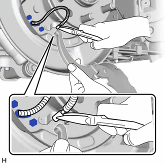
Using needle-nose pliers, connect the No. 3 parking brake cable assembly to the parking brake shoe lever LH as shown in the illustration.
- NOTICE:
-
Be careful not to damage the No. 3 parking brake cable assembly.
5.INSTALL PARKING BRAKE SHOE RETURN TENSION SPRING
Install the parking brake shoe return tension spring to the No. 2 parking brake shoe assembly LH.
6.INSTALL NO. 1 PARKING BRAKE SHOE ASSEMBLY LH
Connect the parking brake shoe return tension spring to install the No. 1 parking brake shoe assembly LH.
7.INSTALL PARKING BRAKE SHOE ADJUSTING SCREW SET
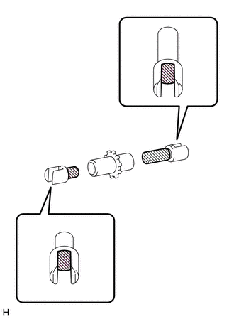
|
|
High-temperature grease |
Apply a light coat of high-temperature grease to the areas of the parking brake shoe adjusting screw set shown in the illustration.
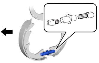

|
Front of the Vehicle |
Install the parking brake shoe adjusting screw set to the No. 1 parking brake shoe assembly LH and No. 2 parking brake shoe assembly LH.
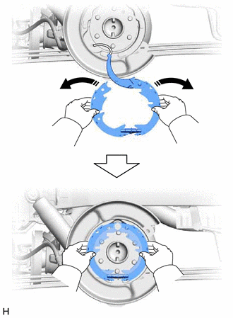
|
|
Expand in this Direction |
Expand the No. 1 and No. 2 parking brake shoe assemblies outward by hand and fit them to the parking brake plate.
8.CONNECT NO. 2 PARKING BRAKE SHOE ASSEMBLY LH
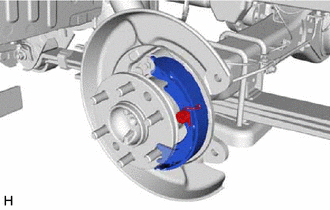
Install the 2 parking brake shoe hold down spring cups and parking brake shoe hold down spring to connect the No. 2 parking brake shoe assembly LH to the backing plate.
9.INSTALL PARKING BRAKE SHOE STRUT COMPRESSION SPRING
Install the parking brake shoe strut compression spring to the parking brake shoe strut LH.
10.INSTALL PARKING BRAKE SHOE STRUT LH
Install the parking brake shoe strut LH.
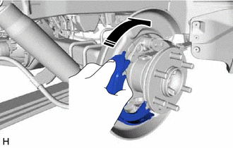
|
|
Push in this Direction |
Push the No. 1 parking brake shoe assembly LH towards the rear of the vehicle by hand as shown in the illustration.
11.CONNECT NO. 1 PARKING BRAKE SHOE ASSEMBLY LH
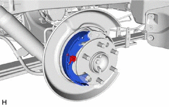
Install the 2 parking brake shoe hold down spring cups and parking brake shoe hold down spring to connect the No. 1 parking brake shoe assembly LH to the backing plate.
12.INSTALL PARKING BRAKE SHOE RETURN TENSION SPRING
- NOTICE:
-
Be sure to install each parking brake shoe return tension spring in the correct position and direction.
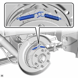
Install the 2 parking brake shoe return tension springs.
- HINT:
-
First install the front side parking brake shoe return tension spring, and then the rear side parking brake shoe return tension spring.
13.CHECK PARKING BRAKE INSTALLATION
Check that each part is installed properly.
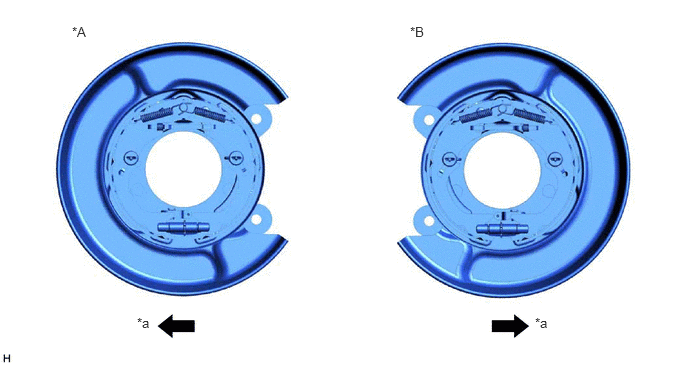
| *A | for LH | *B | for RH |
| *a | Front | - | - |
- NOTICE:
-
There should be no oil or grease on the friction surfaces of the shoe lining and disc.
42431
14.INSTALL REAR DISC
47850
15.CONNECT REAR DISC BRAKE CYLINDER ASSEMBLY LH
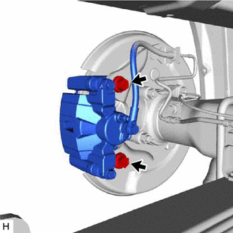
Connect the rear disc brake cylinder assembly LH with the 2 bolts.
- Torque:
- 190 N*m (1937 kgf*cm, 140 ft.*lbf)
16.ADJUST REAR DRUM BRAKE SHOE CLEARANCE
17.CHECK PARKING BRAKE LEVER TRAVEL
18.INSTALL REAR WHEEL
19. BED IN PARKING BRAKE SHOES TO DISCS
Drive the vehicle at about 60 km/h (37 mph) on a safe, level and dry road.
Pull the parking brake lever with a force of 80 N (8 kgf, 18 lbf).
Drive the vehicle for about 170 m (0.106 miles) in this condition.