7GR-FKS ENGINE MECHANICAL REAR CRANKSHAFT OIL SEAL INSTALLATION
PROCEDURE

 11381A
1.INSTALL REAR CRANKSHAFT OIL SEAL
11381A
1.INSTALL REAR CRANKSHAFT OIL SEAL
Apply MP grease to the lip of a new rear crankshaft oil seal.
- NOTICE:
-
Keep the lip free of foreign matter.
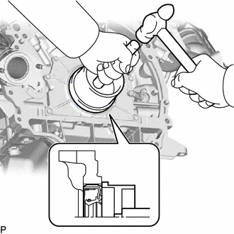
Using SST, tap in a new rear crankshaft oil seal until its surface is flush with the oil seal retainer edge.
- SST
- 09223-15030
09950-70010 (09951-07100)
- NOTICE:
- ·
Keep the lip free of foreign matter.
·Do not tap on the oil seal at an angle.
32101
2.INSTALL DRIVE PLATE AND RING GEAR SUB-ASSEMBLY (for Automatic Transmission)
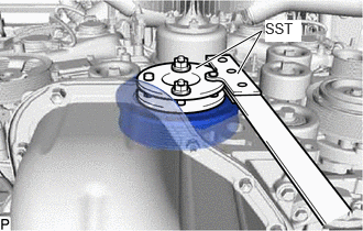
Using SST, hold the crankshaft.
- SST
- 09213-54015 (91651-60855)
09330-00021
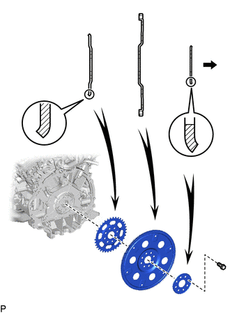
| *1 | No. 1 Crankshaft Position Sensor Plate |
| *2 | Drive Plate and Ring Gear |
| *3 | Rear Drive Plate Spacer |

|
Automatic Transmission Side |
Install the No. 1 crankshaft position sensor plate, drive plate and ring gear sub-assembly and rear drive plate spacer to the crankshaft.
- HINT:
-
As the No. 1 crankshaft position sensor plate, drive plate and ring gear sub-assembly and rear drive plate spacer are not reversible, be sure to install it in the direction shown in the illustration.
Clean the bolts and bolt holes.
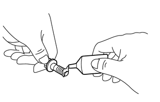
| *a | Adhesive |
Apply adhesive to 2 or 3 threads at the end of the 8 bolts.
- Adhesive:
Toyota Genuine Adhesive 1324, Three Bond 1324 or equivalent
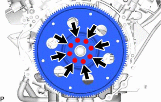
Install and uniformly tighten the 8 bolts in the sequence shown in the illustration.
- Torque:
- 83 N*m (846 kgf*cm, 61 ft.*lbf)
- NOTICE:
-
Do not start the engine for at least an hour after installing the drive plate.
13405
3.INSTALL FLYWHEEL SUB-ASSEMBLY (for Manual Transmission)
Using SST, hold the crankshaft.
- SST
- 09213-54015 (91651-60855)
09330-00021
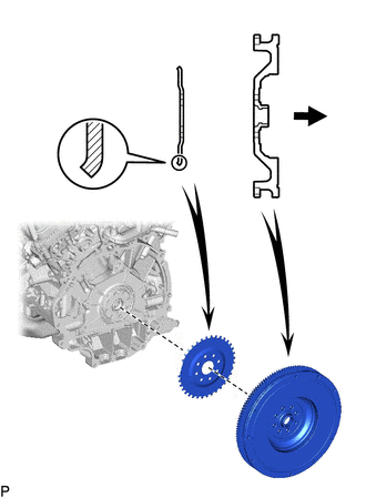
| *1 | No. 1 Crankshaft Position Sensor Plate |
| *2 | Flywheel Sub-assembly |
|
|
Manual Transmission Side |
Install the No. 1 crankshaft position sensor plate and flywheel sub-assembly to the crankshaft.
- HINT:
-
As the No. 1 crankshaft position sensor plate and flywheel sub-assembly are not reversible, be sure to install it in the direction shown in the illustration.
Clean the bolt holes.
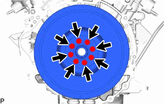
Install the flywheel sub-assembly with 8 new bolts and uniformly tighten the bolts in the sequence shown in the illustration.
- Torque:
- 30 N*m (306 kgf*cm, 22 ft.*lbf)
Mark the top of the bolts with paint.
Tighten the 8 bolts 90° in the same sequence.
Check that the paint marks are now at a 90° angle to the top.
31250
4.INSTALL CLUTCH DISC ASSEMBLY (for Manual Transmission)
31210
5.INSTALL CLUTCH COVER ASSEMBLY (for Manual Transmission)
31210
6.INSPECT AND ADJUST CLUTCH COVER ASSEMBLY (for Manual Transmission)
33030
7.INSTALL MANUAL TRANSMISSION UNIT ASSEMBLY (for Manual Transmission)
35000
8.INSTALL AUTOMATIC TRANSMISSION ASSEMBLY (for Automatic Transmission)