RM35X0E _58 Vehicle Interior _078337 METER / GAUGE / DISPLAY _0379907 METER / GAUGE SYSTEM J

METER / GAUGE / DISPLAY  METER / GAUGE SYSTEM  Entire Combination Meter does not Operate  


DESCRIPTION

This circuit is the power source circuit for the combination meter assembly. This circuit provides two types of power sources; one is a constant power source, and the other is an IG power source.

WIRING DIAGRAM
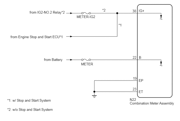
C408706E07
0.417,1.385 2.896,1.885 2.479,0.5 10 false from Engine Stop and Start ECU*1 1.177,0.406 2.604,0.813 1.427,0.406 10 false from IG2-NO.2 Relay*2 3.229,2.469 4.656,2.875 1.427,0.406 10 false METER 4.719,0.917 5.031,1.115 0.313,0.198 10 false *1 4.073,0.323 4.385,0.521 0.313,0.198 10 false *2 5.167,4.031 7.125,4.594 1.958,0.563 10 false Combination Meter Assembly 5.167,3.885 5.625,4.083 0.458,0.198 10 false N22 5.521,0.344 5.979,0.542 0.458,0.198 10 false IG+ 5.271,0.354 5.729,0.552 0.458,0.198 10 false 38 5.531,2.208 5.99,2.406 0.458,0.198 10 false B 5.281,2.208 5.74,2.406 0.458,0.198 10 false 22 5.521,3.125 5.979,3.323 0.458,0.198 10 false EP 5.281,3.469 5.74,3.667 0.458,0.198 10 false 23 3.052,0.583 4.479,0.99 1.427,0.406 10 false METER-IG2 1.75,2.292 3.552,2.781 1.802,0.49 10 false from Battery 0.292,4.281 2.948,4.635 2.656,0.354 10 false *2: w/o Stop and Start System 0.292,3.917 2.948,4.271 2.656,0.354 10 false *1: w/ Stop and Start System 5.521,3.573 5.979,3.771 0.458,0.198 10 false ET 5.292,3.042 5.75,3.24 0.458,0.198 10 false 19

CAUTION / NOTICE / HINT

NOTICE:
·

When replacing the combination meter assembly, always replace it with a new one. If a combination meter assembly which was installed to another vehicle is used, the information stored in it will not match the information from the vehicle and a DTC may be stored.

·

Inspect the fuses of circuits related to this system before performing the following procedure.


PROCEDURE
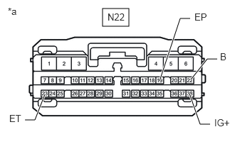
1.CHECK HARNESS AND CONNECTOR (COMBINATION METER ASSEMBLY - BATTERY AND BODY GROUND)
C406366C26
1.5,0.125 1.885,0.385 0.385,0.26 3.073,1.823 2.927,1.823 2.927,1.823 2.771,1.375 true 0.365,1.76 0.51,1.76 0.51,1.76 0.656,1.385 true 2.792,1.167 3.031,0.865 3.031,0.865 3.177,0.865 true 2.333,1.188 2.635,0.271 2.635,0.271 2.781,0.271 true 0.115,0.083 0.427,0.24 0.313,0.156 10 false *a 1.573,0.167 1.885,0.323 0.313,0.156 10 false N22 3.135,1.719 3.427,1.979 0.292,0.26 10 false IG+ 0.135,1.656 0.625,1.854 0.49,0.198 10 false ET 2.844,0.167 3.333,0.365 0.49,0.198 10 false EP 3.219,0.75 3.417,0.948 0.198,0.198 10 false B
*a Front view of wire harness connector
(to Combination Meter Assembly)


a.

Disconnect the combination meter assembly connector.


b.

Measure the resistance according to the value(s) in the table below.

Standard Resistance:
Tester Connection Condition Specified Condition
N22-19 (EP) - Body ground Always Below 1 Ω
N22-23 (ET) - Body ground Always Below 1 Ω


c.

Measure the voltage according to the value(s) in the table below.

Standard Voltage:
Tester Connection Switch Condition Specified Condition

*1: w/ Stop and Start System

*2: w/o Stop and Start System

N22-38 (IG+) - Body ground Ignition switch off Below 1 V
Ignition switch ON 10.5 to 16 V*1
11 to 14 V*2
N22-22 (B) - Body ground Always 11 to 14 V


Result:
Result Proceed to
OK A
NG (IG+ terminal) (w/ Stop and Start System) B
NG (IG+ terminal) (w/o Stop and Start System) C
NG (Other terminal)


A

B

C

REPAIR OR REPLACE HARNESS OR CONNECTOR