EXTERIOR PANELS / TRIM REAR BUMPER(for TFTM Made) REMOVAL
CAUTION / NOTICE / HINT
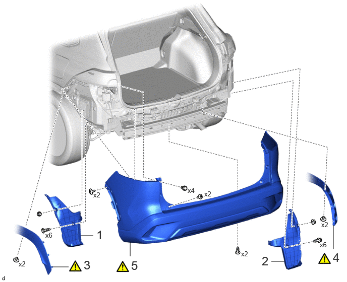
| Procedure | Part Name Code | 
|

|

|
|
|---|---|---|---|---|---|
| 1 | REAR BUMPER SIDE SEAL LH | 52592 | - | - | - |
| 2 | REAR BUMPER SIDE SEAL RH | 52591 | - | - | - |
| 3 | QUARTER OUTSIDE MOULDING SUB-ASSEMBLY LH | 75606B | ( 202307,999999,_59,_114126,_0505909,RM100000002CTJM_01_0070,) 202307,999999,_59,_114126,_0505909,RM100000002CTJM_01_0070,)
|
- | - |
| 4 | QUARTER OUTSIDE MOULDING SUB-ASSEMBLY RH | 75605B | (202307,999999,_59,_114126,_0505909,RM100000002CTJM_01_0070,)
|
- | - |
| 5 | REAR BUMPER ASSEMBLY | - | (202307,999999,_59,_114126,_0505909,RM100000002CTJM_01_0068,)
|
- | - |
CAUTION / NOTICE / HINT
- HINT:
-
When the cable is disconnected/reconnected to the auxiliary battery terminal, systems temporarily stop operating. However, each system has a function that completes learning the first time the system is used.
- ·
Learning completes when vehicle is driven
Effect/Inoperative Function When Necessary Procedures are not Performed Necessary Procedures Link *1: for Gasoline Model
Front camera system Drive the vehicle straight ahead at 15 km/h (10 mph) or more for 1 second or more. ( 202307,999999,_95,_112293,_0586709,RM100000002BSVY,)
Stop and start system*1 Drive the vehicle until stop and start control is permitted (approximately 5 to 60 minutes) ( 202307,999999,_51,_115233,_0510781,RM100000002CS0B,)
·Learning completes when vehicle is operated normally
Effect/Inoperative Function When Necessary Procedures are not Performed Necessary Procedures Link Power door lock control system
·Back door opener
Perform door unlock operation with door control switch or electrical key transmitter sub-assembly switch. ( 202201,999999,_58,_115226,_0510939,RM1000000020BSY,)
Power back door system Fully close the back door by hand.
- HINT:
-
Initialization is not necessary if the above procedures are performed while the back door is closed.
( 202201,999999,_59,_113746,_0504731,RM100000001ZJKP,)
Air conditioning system After the ignition switch is turned to ON, the servo motor standard position is recognized. -
PROCEDURE

 52592
1.REMOVE REAR BUMPER SIDE SEAL LH
52592
1.REMOVE REAR BUMPER SIDE SEAL LH
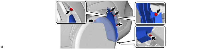
52591
2.REMOVE REAR BUMPER SIDE SEAL RH
Use the same procedure as for the LH side.
75606B
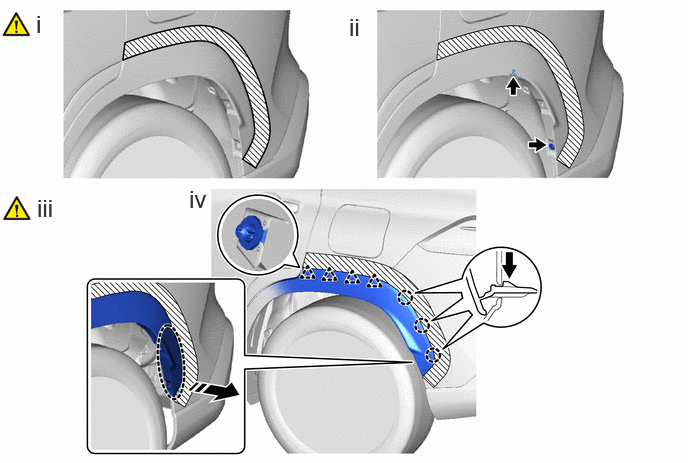
3.SEPARATE QUARTER OUTSIDE MOULDING SUB-ASSEMBLY LH

|
Push | 
|
Place Hand Here |

|
Remove in this Direction | - | - |
Apply protective tape around the quarter outside moulding sub-assembly LH as shown in the illustration.
Remove the 2 clips.
Disengage the claws by pushing the area indicated by the arrow in the illustration with a finger.
- NOTICE:
-
To avoid damaging the claws, do not forcibly pull the quarter outside moulding sub-assembly LH.
Disengage the clips to separate the quarter outside moulding sub-assembly LH from the rear bumper assembly as shown in the illustration.
75605B
4.SEPARATE QUARTER OUTSIDE MOULDING SUB-ASSEMBLY RH
Use the same procedure as for the LH side.
5.REMOVE REAR BUMPER ASSEMBLY
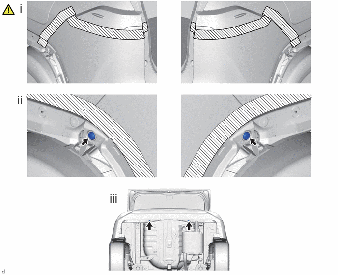
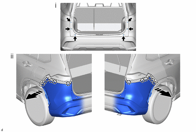
Apply protective tape around the rear bumper assembly as shown in the illustration.
Remove the 2 clips.
Remove the 2 clips.
|
|
Remove in this Direction | - | - |
Remove the 2 rear bumper upper stoppers and 4 screws.
Disengage the claws as shown in the illustration.
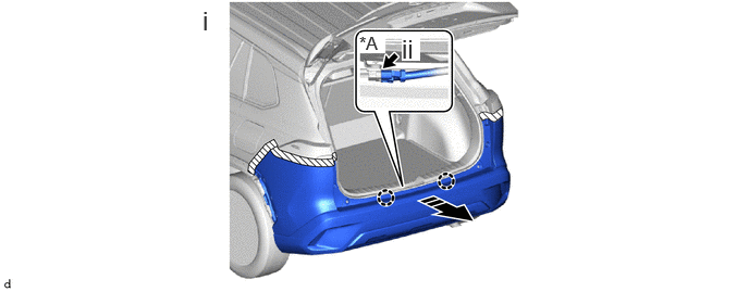
| *A | w/ Wire Harness | - | - |
|
|
Remove in this Direction | - | - |
Disengage the claws to remove the rear bumper assembly as shown in the illustration.
w/ Wire Harness:
1. Disconnect the connector.