EXTERIOR PANELS / TRIM FRONT BUMPER(for TFTM Made) REMOVAL
CAUTION / NOTICE / HINT
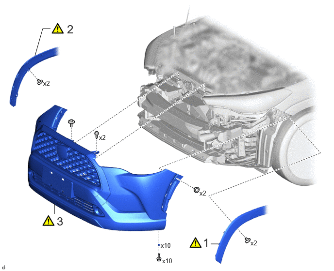
| Procedure | Part Name Code | 
|

|

|
|
|---|---|---|---|---|---|
| 1 | FRONT FENDER MOULDING SUB-ASSEMBLY LH | 75602A | ( 202307,999999,_59,_114126,_0505908,RM100000002CTH8_01_0055,) 202307,999999,_59,_114126,_0505908,RM100000002CTH8_01_0055,)
|
- | - |
| 2 | FRONT FENDER MOULDING SUB-ASSEMBLY RH | 75601A | (202307,999999,_59,_114126,_0505908,RM100000002CTH8_01_0055,)
|
- | - |
| 3 | FRONT BUMPER ASSEMBLY | - | (202307,999999,_59,_114126,_0505908,RM100000002CTH8_01_0053,)
|
- | - |
CAUTION / NOTICE / HINT
The necessary procedures (adjustment, calibration, initialization, or registration) that must be performed after parts are removed and installed, or replaced during front bumper assembly removal/installation are shown below.
| Replaced Part or Performed Procedure | Necessary Procedure | Effect/Inoperative Function when Necessary Procedure not Performed | Link |
|---|---|---|---|
| Front bumper assembly | Television camera view adjustment
|
Panoramic View Monitor System | (202201,999999,_56,_111969,_0587004,RM1000000029RN8,)
|
PROCEDURE

 75602A
1.SEPARATE FRONT FENDER MOULDING SUB-ASSEMBLY LH
75602A
1.SEPARATE FRONT FENDER MOULDING SUB-ASSEMBLY LH
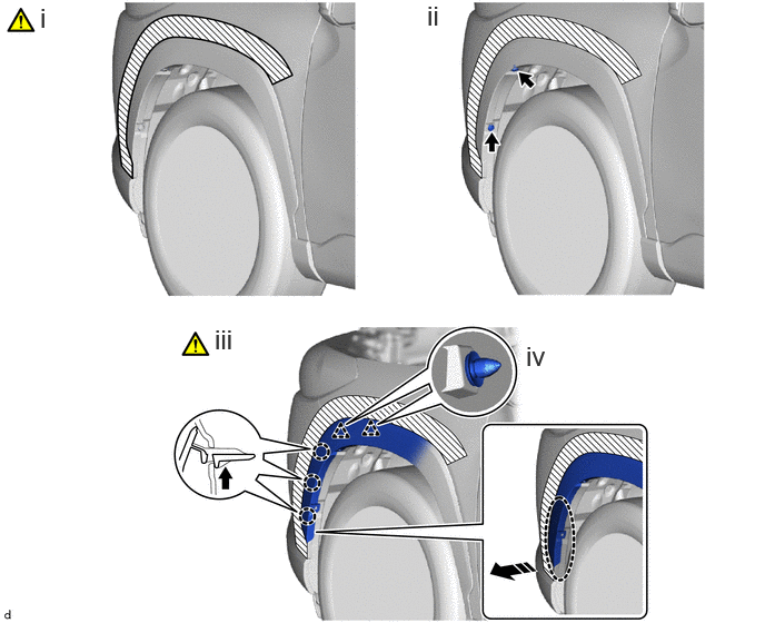

|
Push | 
|
Place Hand Here |

|
Remove in this Direction | - | - |
Apply protective tape around the front fender moulding sub-assembly LH as shown in the illustration.
Remove the 2 clips.
Pull back the edge of the front fender liner LH and disengage the claws by pushing the area indicated by the arrow in the illustration with a finger.
- NOTICE:
- ·
Do not apply excessive force when pulling back the front fender liner LH.
·To avoid damaging the claws, do not forcibly pull the front fender moulding sub-assembly LH.
Disengage the clips and separate the front fender moulding sub-assembly LH as shown in the illustration.
75601A
2.SEPARATE FRONT FENDER MOULDING SUB-ASSEMBLY RH
Use the same procedure as for the LH side.
3.REMOVE FRONT BUMPER ASSEMBLY
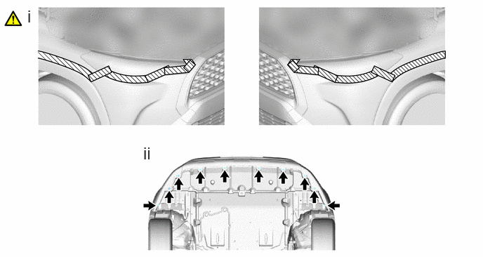
Apply protective tape around the front bumper assembly as shown in the illustration.
Remove the 10 screws.
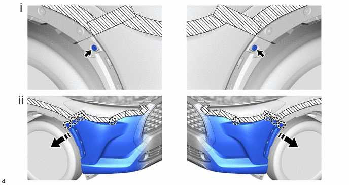
|
|
Remove in this Direction | - | - |
Remove the 2 clips.
Disengage the claws as shown in the illustration.
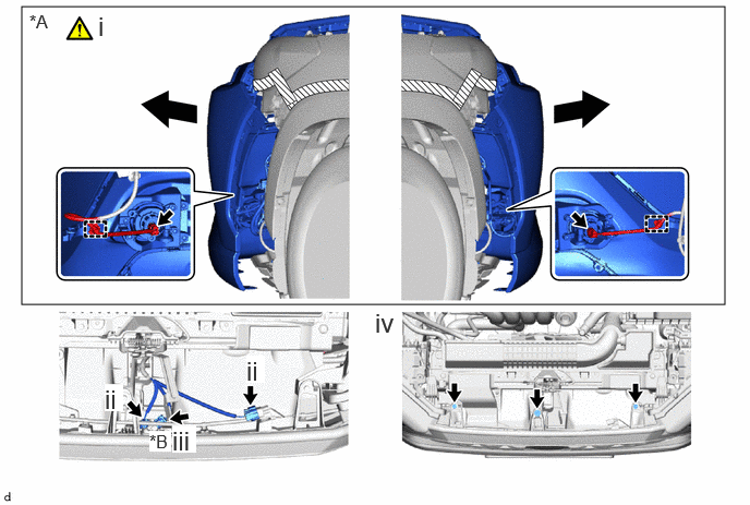
| *A | w/ Fog Light | *B | w/ Panoramic View Monitor System |
|
|
Pull | - | - |
w/ Fog Light:
1. Pull back the side of the front bumper assembly as shown in the illustration.
- NOTICE:
-
Do not apply excessive force when pulling back the front bumper assembly.
2. Disconnect the 2 connectors and disengage the clamps.
Disconnect the 2 connectors.
w/ Panoramic View Monitor System:
1. Disconnect the connector.
Remove the 2 screws and bolt.
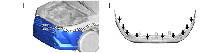
Disengage the guide to remove the front bumper assembly.
Remove the 10 grommets.