BRAKE CONTROL / DYNAMIC CONTROL SYSTEMS ELECTRONICALLY CONTROLLED BRAKE SYSTEM(for HEV Model) Brake Hold Standby Indicator Light Circuit
DESCRIPTION
The brake hold standby indicator light turns on if brake hold control is possible when the following conditions required for operation standby are met and the brake hold switch (electric parking brake switch assembly) is pressed while the ignition switch is ON.
Conditions required for operation standby:
The driver door is closed.
The driver seat belt is fastened.
The system is normal.
WIRING DIAGRAM
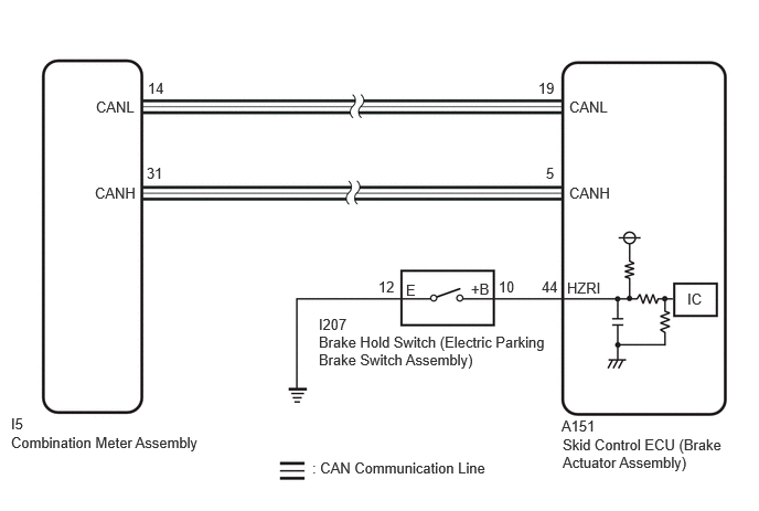
PROCEDURE
If the brake hold standby indicator light does not illuminate even though the brake hold switch (electric parking brake switch assembly) is pushed, check that the brake hold function operation conditions are met.
The driver door is closed.
The driver seat belt is fastened.
The system is normal.
- HINT:
-
If a malfunction occurs in one of the following systems, the brake hold operated indicator light will blink. If this occurs, perform troubleshooting on the malfunctioning system.
- ·
Electronically controlled brake system
·Electric parking brake system
·Hybrid control system
- Result:
Proceed to NEXT
NEXT
Operate the GTS to read the Data List.
- Chassis > Brake/EPB > Data List
-
Tester Display Measurement Item Range Normal Condition Diagnostic Note Brake Hold Ready Brake hold control permission status Not in stand-by mode / Stand-by mode Not in stand-by mode: Brake hold function not operating (brake hold indicator not illuminated)
Stand-by mode: Brake hold function stand-by state (brake hold indicator illuminated)-
- Chassis > Brake/EPB > Data List
-
Tester Display Brake Hold Ready - 50003 435 164
Check the brake hold standby indicator light and mode condition on the GTS changes according to brake hold switch (electric parking brake switch assembly) operation.
- Standard:
Brake Hold Switch (Electric Parking Brake Switch Assembly) Operation Mode Condition Display Brake Hold Standby Indicator Light Not pressed Not in stand-by mode Does not come on Pressing the brake hold switch (electric parking brake switch assembly) Stand-by mode Comes on
- Result:
Result Proceed to Indicator light and mode condition display do not change A Mode condition display is normal, but indicator light does not change B Indicator light and mode condition display are normal C
A
B
C
Turn the ignition switch off.
Inspect the brake hold switch (electric parking brake switch assembly).
- OK:
The brake hold switch (electric parking brake switch assembly) is normal.
- Result:
Proceed to OK NG
OK
NG
Make sure that there is no looseness at the locking part and the connecting part of the connector.
- OK:
The connector is securely connected.
Disconnect the A151 skid control ECU (brake actuator assembly) connector.
Disconnect the I207 brake hold switch (electric parking brake switch assembly) connector.
Check both the connector case and the terminal for deformation and corrosion.
- OK:
No deformation or corrosion.
Measure the resistance according to the value(s) in the table below.
- Standard Resistance:
Tester Connection Condition Specified Condition I207-10 (+B) - A151-44 (HZRI) Always Below 1 Ω I207-10 (+B) or A151-44 (HZRI) - Body ground Always 10 kΩ or higher I207-12 (E) - Body ground 1 minute or more after disconnecting the cable from the negative (-) auxiliary battery terminal Below 1 Ω
- Result:
Proceed to OK NG
OK
NG