BRAKE CONTROL / DYNAMIC CONTROL SYSTEMS ELECTRONICALLY CONTROLLED BRAKE SYSTEM(for HEV Model) C121F87 Electronic Brake Booster Control Module "A" Missing Message C136E17 Electronic Brake Booster Control Module "A" Backup Power Supply Voltage Circuit Voltage Above Threshold C136E1E Electronic Brake Booster Control Module "A" Backup Power Supply Voltage Circuit Resistance Out of Range C136E49 Electronic Brake Booster Control Module "A" Backup Power Supply Voltage Internal Electronic Failure C137A04 Electronic Brake Booster Control Module "A" Backup Power Supply Module System Internal Failure C137A17 Electronic Brake Booster Control Module "A" Backup Power Supply Module Circuit Voltage Above Threshold C137A49 Electronic Brake Booster Control Module "A" Backup Power Supply Module Internal Electronic Failure C137A86 Electronic Brake Booster Control Module "A" Backup Power Supply Module Signal (some circuit quantity, reported via serial data) Invalid C137A87 Electronic Brake Booster Control Module "A" Backup Power Supply Module Missing Message C13BE00 Electronic Brake Booster Control Module "A" Backup Power Supply Module Charging Circuit C13BE49 Electronic Brake Booster Control Module "A" Backup Power Supply Module Charging Circuit Internal Electronic Failure C13DF1C Electronic Brake Booster Control Module "A" Backup Power Supply Module Circuit Voltage Out of Range C13FC49 Electronic Brake Booster Control Module "A" Internal Electronic Failure C13FD12 Electronic Brake Booster Control Module "A" Backup Power Supply Module Discharge Circuit Circuit Short to Battery C13FD14 Electronic Brake Booster Control Module "A" Backup Power Supply Module Discharge Circuit Circuit Short to Ground or Open C148E1C Electronic Brake Booster Control Module "A" Backup Power Supply Module Sensor Circuit Voltage Out of Range C14BF49 Electronic Brake Booster Control Module "A" Backup Power Supply Module Backup Circuit Internal Electronic Failure C14CC1C Electronic Brake Booster Control Module "A" Backup Power Supply Module Temperature Sensor Circuit Voltage Out of Range
DESCRIPTION
The brake control power supply assembly is used as an auxiliary power supply for brake control when the voltage of the auxiliary battery is low.
| DTC No. | Detection Item | DTC Detection Condition | Trouble Area | MIL | DTC Output from | Note |
|---|---|---|---|---|---|---|
| C121F87 | Electronic Brake Booster Control Module "A" Missing Message | During IG ON, a brake control power supply assembly internal malfunction is detected. | ·
Wire harness or connector ·
Brake control power supply assembly |
Does not come on | Brake Booster | Output ECU: Electric brake booster (brake booster with master cylinder assembly) |
| C136E17 | Electronic Brake Booster Control Module "A" Backup Power Supply Voltage Circuit Voltage Above Threshold | During IG ON, a brake control power supply assembly cell malfunction is detected. | ·
Wire harness or connector ·
Brake control power supply assembly |
Does not come on | Brake Booster | Output ECU: Electric brake booster (brake booster with master cylinder assembly) |
| C136E1E | Electronic Brake Booster Control Module "A" Backup Power Supply Voltage Circuit Resistance Out of Range | During IG ON, brake control power supply assembly degradation (end-of-life notification) is detected. | ·
Wire harness or connector ·
Brake control power supply assembly |
Does not come on | Brake Booster | Output ECU: Electric brake booster (brake booster with master cylinder assembly) |
| C136E49 | Electronic Brake Booster Control Module "A" Backup Power Supply Voltage Internal Electronic Failure | During IG ON, the brake control power supply assembly self-discharge amount (current leak) is detected to be excessive (internal malfunction). | ·
Wire harness or connector ·
Brake control power supply assembly |
Does not come on | Brake Booster | Output ECU: Electric brake booster (brake booster with master cylinder assembly) |
| C137A04 | Electronic Brake Booster Control Module "A" Backup Power Supply Module System Internal Failure | During IG ON, a brake control power supply assembly internal malfunction is detected. | ·
Wire harness or connector ·
Brake control power supply assembly |
Does not come on | Brake Booster | Output ECU: Electric brake booster (brake booster with master cylinder assembly) |
| C137A17 | Electronic Brake Booster Control Module "A" Backup Power Supply Module Circuit Voltage Above Threshold | During IG ON, a brake control power supply assembly overvoltage malfunction is detected. | ·
Wire harness or connector ·
Brake control power supply assembly |
Does not come on | Brake Booster | Output ECU: Electric brake booster (brake booster with master cylinder assembly) |
| C137A49 | Electronic Brake Booster Control Module "A" Backup Power Supply Module Internal Electronic Failure | During IG ON, a brake control power supply assembly power source circuit malfunction is detected. | ·
Wire harness or connector ·
Brake control power supply assembly |
Does not come on | Brake Booster | Output ECU: Electric brake booster (brake booster with master cylinder assembly) |
| C137A86 | Electronic Brake Booster Control Module "A" Backup Power Supply Module Signal (some circuit quantity, reported via serial data) Invalid | While driving at a vehicle speed of 3 km/h or more, LIN communication from brake control power supply assembly is abnormal for 10 seconds or more. | ·
Wire harness or connector ·
Brake control power supply assembly |
Does not come on | Brake Booster | Output ECU: Electric brake booster (brake booster with master cylinder assembly) |
| C137A87 | Electronic Brake Booster Control Module "A" Backup Power Supply Module Missing Message | LIN communication with brake control power supply assembly is abnormal for 0.5 seconds or more. | ·
Wire harness or connector ·
Brake control power supply assembly |
Does not come on | Brake Booster | Output ECU: Electric brake booster (brake booster with master cylinder assembly) |
| C13BE00 | Electronic Brake Booster Control Module "A" Backup Power Supply Module Charging Circuit | During IG ON, a brake control power supply assembly power source backup unit internal circuit (backup output circuit) failure is detected. | ·
Wire harness or connector ·
Brake control power supply assembly |
Does not come on | Brake Booster | Output ECU: Electric brake booster (brake booster with master cylinder assembly) |
| C13BE49 | Electronic Brake Booster Control Module "A" Backup Power Supply Module Charging Circuit Internal Electronic Failure | During IG ON, a brake control power supply assembly charging circuit malfunction is detected. | ·
Wire harness or connector ·
Brake control power supply assembly |
Does not come on | Brake Booster | Output ECU: Electric brake booster (brake booster with master cylinder assembly) |
| C13DF1C | Electronic Brake Booster Control Module "A" Backup Power Supply Module Circuit Voltage Out of Range | During IG ON, a brake control power supply assembly power source malfunction is detected. | ·
Wire harness or connector ·
Brake control power supply assembly |
Does not come on | Brake Booster | Output ECU: Electric brake booster (brake booster with master cylinder assembly) |
| C13FC49 | Electronic Brake Booster Control Module "A" Internal Electronic Failure | LIN communication from brake control power supply assembly is abnormal for 0.1 seconds or more. | ·
Wire harness or connector ·
Brake control power supply assembly |
Does not come on | Brake Booster | Output ECU: Electric brake booster (brake booster with master cylinder assembly) |
| C13FD12 | Electronic Brake Booster Control Module "A" Backup Power Supply Module Discharge Circuit Circuit Short to Battery | During IG ON, a brake control power supply assembly discharging circuit malfunction is detected. | ·
Wire harness or connector ·
Brake control power supply assembly |
Does not come on | Brake Booster | Output ECU: Electric brake booster (brake booster with master cylinder assembly) |
| C13FD14 | Electronic Brake Booster Control Module "A" Backup Power Supply Module Discharge Circuit Circuit Short to Ground or Open | During IG ON, a brake control power supply assembly discharging circuit malfunction is detected. | ·
Wire harness or connector ·
Brake control power supply assembly |
Does not come on | Brake Booster | Output ECU: Electric brake booster (brake booster with master cylinder assembly) |
| C148E1C | Electronic Brake Booster Control Module "A" Backup Power Supply Module Sensor Circuit Voltage Out of Range | During IG ON, a brake control power supply assembly internal circuit malfunction is detected. | ·
Wire harness or connector ·
Brake control power supply assembly |
Does not come on | Brake Booster | Output ECU: Electric brake booster (brake booster with master cylinder assembly) |
| C14BF49 | Electronic Brake Booster Control Module "A" Backup Power Supply Module Backup Circuit Internal Electronic Failure | During IG ON, a brake control power supply assembly backup circuit malfunction is detected. | ·
Wire harness or connector ·
Brake control power supply assembly |
Does not come on | Brake Booster | Output ECU: Electric brake booster (brake booster with master cylinder assembly) |
| C14CC1C | Electronic Brake Booster Control Module "A" Backup Power Supply Module Temperature Sensor Circuit Voltage Out of Range | During IG ON, a brake control power supply assembly power source backup unit internal circuit (voltage monitor circuit) failure is detected. | ·
Wire harness or connector ·
Brake control power supply assembly |
Does not come on | Brake Booster | Output ECU: Electric brake booster (brake booster with master cylinder assembly) |
WIRING DIAGRAM
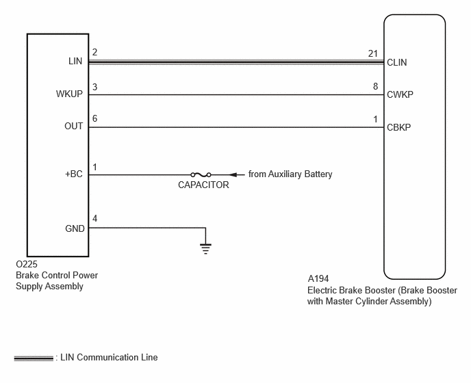
CAUTION / NOTICE / HINT
- NOTICE:
-
Inspect the fuses for circuits related to this system before performing the following procedure.
PROCEDURE
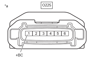
| *a | Front view of wire harness connector
(to Brake Control Power Supply Assembly) |
Make sure that there is no looseness at the locking part and the connecting part of the connectors.
- OK:
The connector is securely connected.
Disconnect the O225 brake control power supply assembly connector.
Check both the connector case and the terminals for deformation and corrosion.
- OK:
No deformation or corrosion.
Measure the voltage according to the value(s) in the table below.
- Standard Voltage:
Tester Connection Condition Specified Condition O225-1 (+BC) - Body ground Always 11 to 14 V
- Result:
Proceed to OK NG
OK
NG
Make sure that there is no looseness at the locking part and the connecting part of the connectors.
- OK:
The connector is securely connected.
Disconnect the O225 brake control power supply assembly connector.
Check both the connector case and the terminals for deformation and corrosion.
- OK:
No deformation or corrosion.
Measure the resistance according to the value(s) in the table below.
- Standard Resistance:
Tester Connection Condition Specified Condition O225-4 (GND) - Body ground 1 minute or more after disconnecting the cable from the negative (-) auxiliary battery terminal Below 1 Ω
- Result:
Proceed to OK NG
OK
NG
Make sure that there is no looseness at the locking part and the connecting part of the connectors.
- OK:
The connector is securely connected.
Disconnect the A194 electric brake booster (brake booster with master cylinder assembly) connector.
Disconnect the O225 brake control power supply assembly connector.
Check both the connector case and the terminals for deformation and corrosion.
- OK:
No deformation or corrosion.
Measure the resistance according to the value(s) in the table below.
- Standard Resistance:
Tester Connection Condition Specified Condition A194-21 (CLIN) - O225-2 (LIN) Always Below 1 Ω A194-21 (CLIN) or O225-2 (LIN) - Body ground and other terminals Always 10 kΩ or higher A194-1 (CBKP) - O225-6 (OUT) Always Below 1 Ω A194-1 (CBKP) or O225-6 (OUT) - Body ground and other terminals Always 10 kΩ or higher A194-8 (CWKP) - O225-3 (WKUP) Always Below 1 Ω A194-8 (CWKP) or O225-3 (WKUP) - Body ground and other terminals Always 10 kΩ or higher
- Result:
Proceed to OK NG
OK
NG