THEFT DETERRENT / KEYLESS ENTRY SMART ENTRY AND START SYSTEM(for Start Function, HEV Model) B227411 ACC Circuit Short to Ground
DESCRIPTION
This DTC is stored when a malfunction in the ACC output circuit is detected. The ACC output circuit is the circuit between terminal ACCD of the certification ECU (smart key ECU assembly) and the ACC relay.
| DTC No. | Detection Item | DTC Detection Condition | Trouble Area | Note |
|---|---|---|---|---|
| B227411 | ACC Circuit Short to Ground | The ACC relay circuit of the certification ECU (smart key ECU assembly) is malfunctioning. (1-trip detection logic*)
|
·
Power distribution box assembly ·
Certification ECU (smart key ECU assembly) ·
Wire harness or connector |
DTC Output Confirmation Operation:
Wait 10 seconds after turning the ignition switch to ACC or ON, and then wait another 10 seconds after turning the ignition switch off. |
*: Only detected while a malfunction is present.
| Vehicle Condition when Malfunction Detected | Fail-safe Function when Malfunction Detected |
|---|---|
·
If there is a malfunction due to the ACC relay being stuck on, the ACC relay does not turn off even though the ignition switch is off. ·
If there is a malfunction due to the ACC relay being stuck off, the ACC relay does not turn on even though the ignition switch is ACC.
|
- |
| DTC No. | Data List and Active Test |
|---|---|
| B227411 | Power Source Control
·
ACC Relay Monitor |
WIRING DIAGRAM
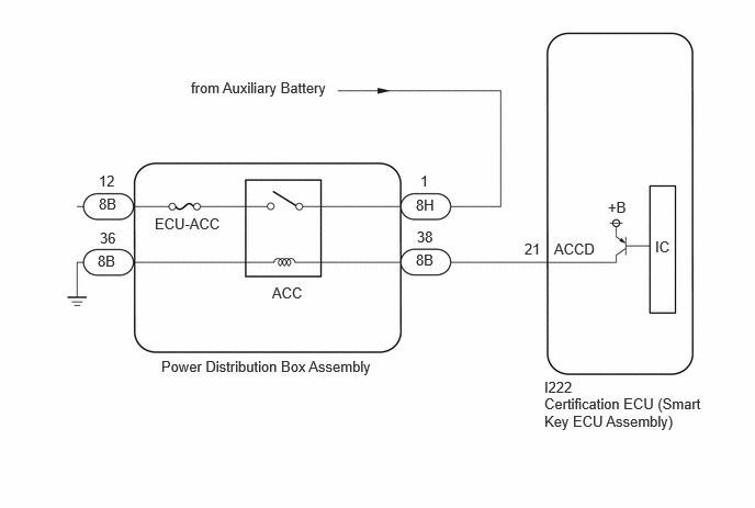
CAUTION / NOTICE / HINT
- NOTICE:
- ·
When using the GTS with the ignition switch off, connect the GTS to the DLC3 and turn a courtesy light switch on and off at intervals of 1.5 seconds or less until communication between the GTS and the vehicle begins. Then select Model Code "KEY REGIST" under manual mode and enter the following menus: Body Electrical / Entry&Start(CAN). While using the GTS, periodically turn a courtesy light switch on and off at intervals of 1.5 seconds or less to maintain communication between the GTS and the vehicle.
·The smart entry and start system (for Start Function) uses the LIN communication system and CAN communication system. Inspect the communication function by following How to Proceed with Troubleshooting. Troubleshoot the smart entry and start system (for Start Function) after confirming that the communication systems are functioning properly.
·Inspect the fuses for circuits related to this system before performing the following procedure.
·Before replacing the certification ECU (smart key ECU assembly), refer to Service Bulletin.
·After repair, confirm that no DTCs are output by performing "DTC Output Confirmation Operation".
PROCEDURE
Disconnect the I222 certification ECU (smart key ECU assembly) connector.
Disconnect the 8B power distribution box assembly connector.
Measure the resistance according to the value(s) in the table below.
- Standard Resistance:
Tester Connection Condition Specified Condition I222-21 (ACCD) - 8B-38 Always Below 1 Ω 8B-36 - Body ground Always Below 1 Ω I222-21 (ACCD) or 8B-38 - Other terminals and body ground Always 10 kΩ or higher
- Result:
Proceed to OK NG
OK
NG
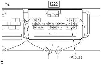
| *a | Component with harness connected
(Certification ECU (Smart Key ECU Assembly)) |
Measure the voltage according to the value(s) in the table below.
- Standard Voltage:
Tester Connection Switch Condition Specified Condition I222-21 (ACCD) - Body ground Ignition switch off 1 V or less I222-21 (ACCD) - Body ground Ignition switch ACC 8.5 V or higher
- Result:
Proceed to OK NG
OK
NG