BRAKE SYSTEM (OTHER) VACUUM PUMP(for BOSCH Made) REMOVAL
CAUTION / NOTICE / HINT
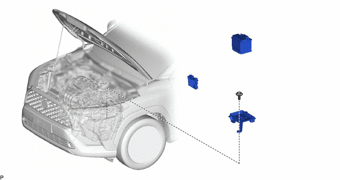
| Procedure | Part Name Code | 
|

|

|
|
|---|---|---|---|---|---|
| 1 | ECM | 89661 | - | - | - |
| 2 | AUXILIARY BATTERY | - | - | - | - |
| 3 | BATTERY CLAMP SUB-ASSEMBLY | 74404A | - | - | - |
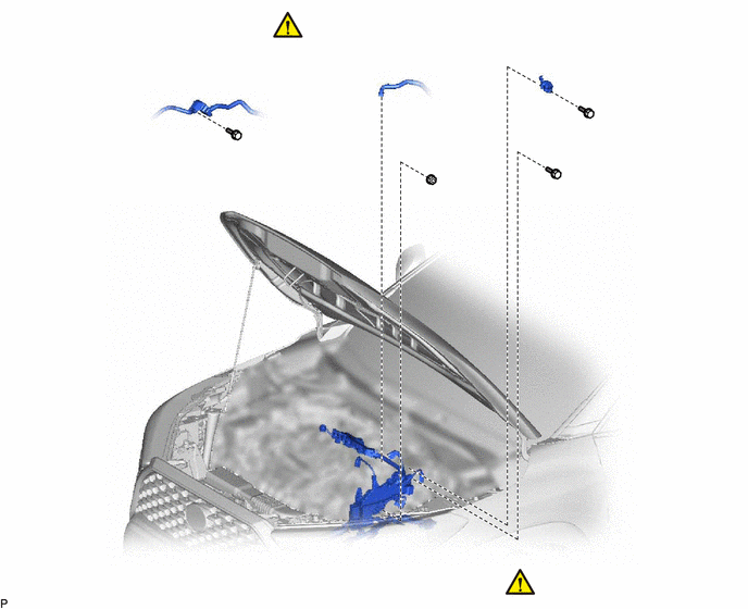
| Procedure | Part Name Code |
|
|
|
|
|---|---|---|---|---|---|
| 4 | NO. 1 VACUUM HOSE CONNECTOR | 44777 | ( 202307,999999,_54,_113942,_0505309,RM100000002C1CM_01_0022,) 202307,999999,_54,_113942,_0505309,RM100000002C1CM_01_0022,)
|
- | - |
| 5 | ENGINE WIRE | 82121 | (202307,999999,_54,_113942,_0505309,RM100000002C1CM_01_0038,)
|
- | - |
| 6 | VACUUM SURGE TANK | 25719 | - | - | - |
| 7 | NO. 3 WATER HOSE CLAMP BRACKET | 16575F | - | - | - |
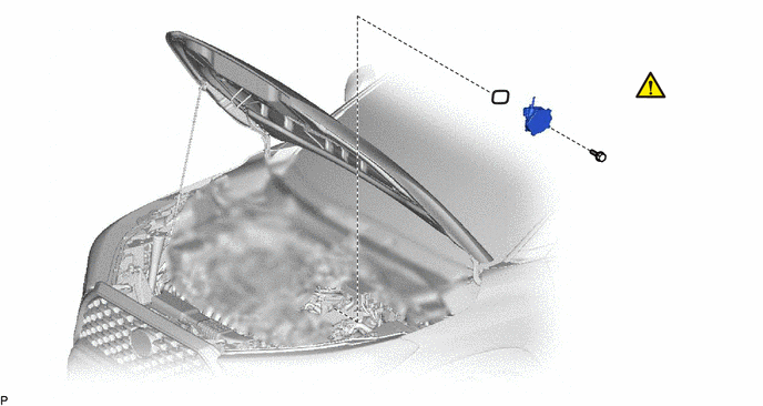
| Procedure | Part Name Code |
|
|
|
|
|---|---|---|---|---|---|
| 8 | VACUUM PUMP ASSEMBLY | 29300 | (202307,999999,_54,_113942,_0505309,RM100000002C1CM_01_0002,)
|
- | - |
| *1 | NO. 1 VACUUM PUMP O-RING | - | - |
| ● | Non-reusable part | - | - |
CAUTION / NOTICE / HINT
The necessary procedures (adjustment, calibration, initialization or registration) that must be performed after parts are removed and installed, or replaced during vacuum pump assembly removal/installation are shown below.
- HINT:
-
When the cable is disconnected/reconnected to the auxiliary battery terminal, systems temporarily stop operating. However, each system has a function that completes learning the first time the system is used.
- ·
Learning completes when vehicle is driven
Effect/Inoperative Function When Necessary Procedures are not Performed Necessary Procedures Link Front camera system Drive the vehicle straight ahead at 15 km/h (10 mph) or more for 1 second or more. ( 202307,999999,_95,_112293,_0586709,RM100000002BSVY,)
Stop and start system Drive the vehicle until stop and start control is permitted (approximately 5 to 60 minutes). ( 202307,999999,_51,_115233,_0510781,RM100000002CS0B,)
·Learning completes when vehicle is operated normally
Effect/Inoperative Function When Necessary Procedures are not Performed Necessary Procedures Link Power door lock control system
·Back door opener
Perform door unlock operation with door control switch or electrical key transmitter sub-assembly switch. ( 202201,999999,_58,_115226,_0510939,RM1000000020BSY,)
Power back door system Fully close the back door by hand.
- HINT:
-
Initialization is not necessary if the above procedures are performed while the back door is closed.
( 202201,999999,_59,_113746,_0504731,RM100000001ZJKP,)
Air conditioning system After the ignition switch is turned to ON, the servo motor standard position is recognized. -
CAUTION / NOTICE / HINT
- NOTICE:
-
This procedure includes the removal of small-head bolts. Refer to Small-Head Bolts of Basic Repair Hint to identify the small-head bolts.
- HINT:
-
Refer to the following illustration and check which type is installed to the vehicle.
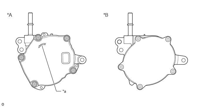 2.167,3.25 2,3.25 2,3.25 1.479,1.594 true 0.25,0.427 0.625,0.667 0.375,0.24 12 false *A 3.667,0.427 4.042,0.667 0.375,0.24 12 false *B 2.219,3.167 2.531,3.365 0.313,0.198 10 false *a
*A for BOSCH Made *B except BOSCH Made *a Mark - -
PROCEDURE

 89661
1.REMOVE ECM
89661
1.REMOVE ECM
2.REMOVE AUXILIARY BATTERY
74404A
3.REMOVE BATTERY CLAMP SUB-ASSEMBLY
44777
4.DISCONNECT NO. 1 VACUUM HOSE CONNECTOR
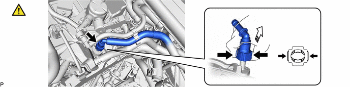
| *a | Retainer | - | - |

|
Pinch | 
|
Pull off |
Pinch the retainer of the No. 1 vacuum hose connector, and then pull off the No. 1 vacuum hose connector of the vacuum pump assembly.
- NOTICE:
-
Be sure to disconnect the No. 1 vacuum hose connector by hand.
82121
5.SEPARATE ENGINE WIRE
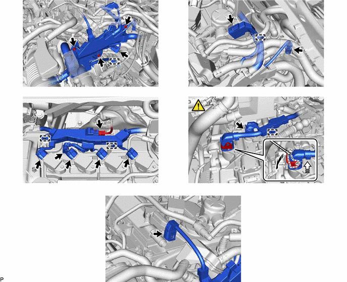
| *a | Protective Tape | - | - |

|
Release the lock lever |
|
Disconnect the connector |
Disconnect the connector and disengage the clamp.
Remove the bolt and 2 nuts, and separate the engine wire.
Disconnect the 2 connectors and disengage the clamp.
Disconnect the 6 connectors and disengage the 2 clamps.
Release the lock lever and disconnect the connector.
Disconnect the connector and disengage the clamp.
Disconnect the connector.
25719
6.REMOVE VACUUM SURGE TANK

16575F
7.REMOVE NO. 3 WATER HOSE CLAMP BRACKET
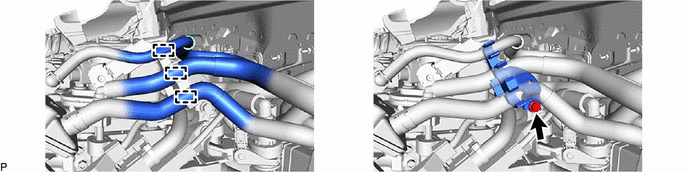
29300
8.REMOVE VACUUM PUMP ASSEMBLY

Move aside the engine wire.
- NOTICE:
-
Do not apply excessive force to the engine wire.
Using an 8 mm socket wrench, remove the 3 bolts and vacuum pump assembly from the engine assembly.
Remove the No. 1 vacuum pump O-ring from the vacuum pump assembly.