NETWORKING CAN COMMUNICATION SYSTEM(for HEV Model) Power Back Door ECU Communication Stop Mode
DESCRIPTION
| Detection Item | Symptom | Trouble Area |
|---|---|---|
| Power Back Door ECU Communication Stop Mode | Communication stop for "Back Door" is indicated on the "Communication Bus Check" screen of the GTS.
Click here(  202307,999999,_57,_104409,_0606038,RM100000002C0LE,) 202307,999999,_57,_104409,_0606038,RM100000002C0LE,)
|
·
Multiplex network door ECU branch line or connector ·
Power source circuit of multiplex network door ECU ·
Multiplex network door ECU ground circuit ·
Multiplex network door ECU |
WIRING DIAGRAM
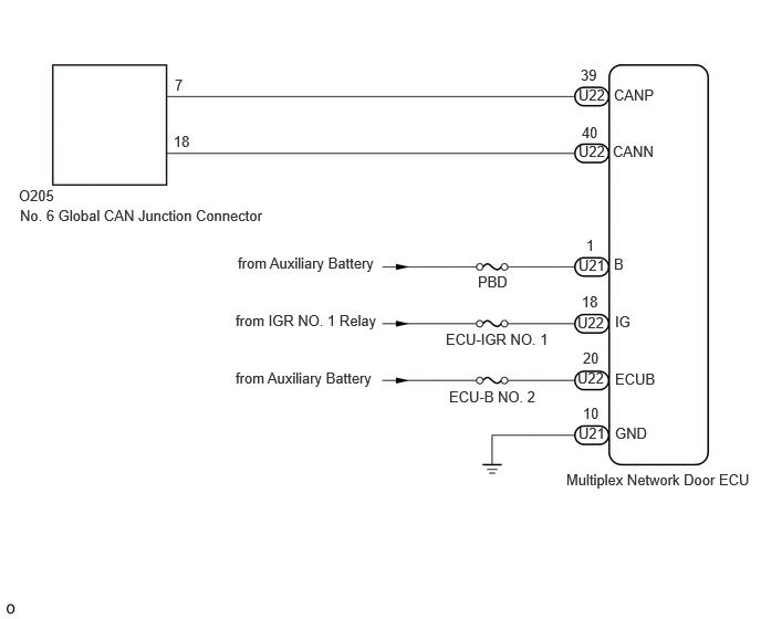
CAUTION / NOTICE / HINT
- CAUTION:
-
When performing the confirmation driving pattern, obey all speed limits and traffic laws.
- NOTICE:
- ·
Because the order of diagnosis is important to allow correct diagnosis, make sure to begin troubleshooting using How to Proceed with Troubleshooting when CAN communication system related DTCs are output.
·Before measuring the resistance of the CAN bus, turn the ignition switch off and leave the vehicle for 1 minute or more without operating the key or any switches, or opening or closing the doors. After that, disconnect the cable from the negative (-) auxiliary battery terminal and leave the vehicle for 10 minute or more before measuring the resistance.
·After the ignition switch is turned off, there may be a waiting time before disconnecting the negative (-) auxiliary battery terminal.
·When disconnecting and reconnecting the auxiliary battery.
- HINT:
-
When disconnecting and reconnecting the auxiliary battery, there is an automatic learning function that completes learning when the respective system is used.
·Some parts must be initialized and set when replacing or removing and installing parts.
·After performing repairs, perform the DTC check procedure and confirm that the DTCs are not output again.
DTC check procedure: Turn the ignition switch to ON and wait for 1 minute or more. Then operate the suspected malfunctioning system and drive the vehicle at 60 km/h (37 mph) or more for 5 minutes or more.
·After the repair, perform the CAN bus check and check that all the ECUs and sensors connected to the CAN communication system are displayed as normal.
·Inspect the fuses for circuits related to this system before performing the following procedure.
- HINT:
- ·
Before disconnecting related connectors for inspection, push in on each connector body to check that the connector is not loose or disconnected.
·When a connector is disconnected, check that the terminals and connector body are not cracked, deformed or corroded.
PROCEDURE
Disconnect the cable from the negative (-) auxiliary battery terminal.
Disconnect the multiplex network door ECU connector.
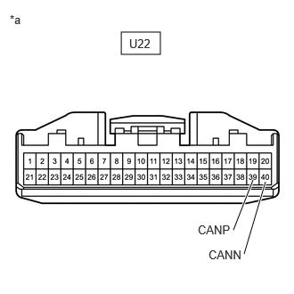
| *a | Front view of wire harness connector
(to Multiplex Network Door ECU) |
Measure the resistance according to the value(s) in the table below.
- Standard Resistance:
Tester Connection Condition Specified Condition U22-39 (CANP) - U22-40 (CANN) Cable disconnected from negative (-) auxiliary battery terminal 54 to 69 Ω
- Result:
Proceed to OK NG
OK
NG
Disconnect the multiplex network door ECU connector.
Measure the resistance according to the value(s) in the table below.
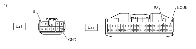
| *a | Front view of wire harness connector
(to Multiplex Network Door ECU) |
- | - |
- Standard Resistance:
Tester Connection Condition Specified Condition U21-10 (GND) - Body ground Cable disconnected from negative (-) auxiliary battery terminal Below 1 Ω
Reconnect the cable to the negative (-) auxiliary battery terminal.
Measure the voltage according to the value(s) in the table below.
- Standard Voltage:
Tester Connection Switch Condition Specified Condition U22-20 (ECUB) - Body ground Ignition switch off 11 to 14 V U21-1 (B) - Body ground Ignition switch off 11 to 14 V U22-18 (IG) - Body ground Ignition switch ON 11 to 14 V
- Result:
Proceed to OK NG
OK
NG