FRONT SUSPENSION FRONT STABILIZER BAR INSTALLATION
CAUTION / NOTICE / HINT
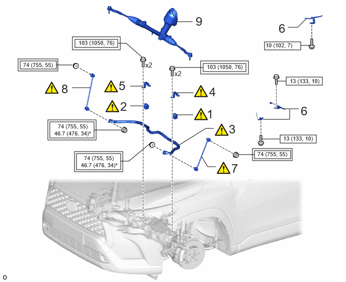
| Procedure | Part Name Code | 
|

|

|
|
|---|---|---|---|---|---|
| 1 | FRONT STABILIZER BAR BUSH LH | 48815E | ( 202307,999999,_53,_112966,_0502994,RM100000002BYS4_01_0050,) 202307,999999,_53,_112966,_0502994,RM100000002BYS4_01_0050,)
|
- | - |
| 2 | FRONT STABILIZER BAR BUSH RH | 48815D | (202307,999999,_53,_112966,_0502994,RM100000002BYS4_01_0051,)
|
- | - |
| 3 | FRONT STABILIZER BAR | 48811 | (202307,999999,_53,_112966,_0502994,RM100000002BYS4_01_0046,)
|
- | - |
| 4 | FRONT NO. 1 STABILIZER BRACKET LH | 48829A | (202307,999999,_53,_112966,_0502994,RM100000002BYS4_01_0052,)
|
- | - |
| 5 | FRONT NO. 1 STABILIZER BRACKET RH | 48824A | (202307,999999,_53,_112966,_0502994,RM100000002BYS4_01_0053,)
|
- | - |
| 6 | WIRE HARNESS CLAMP BRACKET | - | - | - | - |
| 7 | FRONT STABILIZER LINK ASSEMBLY LH | 48810 | (202307,999999,_53,_112966,_0502994,RM100000002BYS4_01_0047,)
|
- | - |
| 8 | FRONT STABILIZER LINK ASSEMBLY RH | 48820B | (202307,999999,_53,_112966,_0502994,RM100000002BYS4_01_0048,)
|
- | - |
| 9 | STEERING LINK ASSEMBLY | - | - | - | - |

|
Tightening torque for "Major areas involving basic vehicle performance such as moving/turning/stopping" : N*m (kgf*cm, ft.*lbf) | 
|
N*m (kgf*cm, ft.*lbf): Specified torque |
| * | For use with a ball joint lock nut wrench | - | - |
PROCEDURE

 48815E
1.INSTALL FRONT STABILIZER BAR BUSH LH
48815E
1.INSTALL FRONT STABILIZER BAR BUSH LH
|
|
|
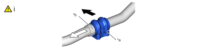
| *a | Cutout | *b | Stopper |

|
Front of the Vehicle | 
|
Outside of the Vehicle |
Install the front stabilizer bar bush LH to the front stabilizer bar as shown in the illustration.
48815D
2.INSTALL FRONT STABILIZER BAR BUSH RH
48811
3.INSTALL FRONT STABILIZER BAR

|
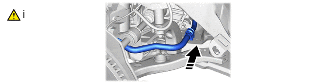
Install in this Direction | - | - |
Install the front stabilizer bar with the 2 front stabilizer bar bushes to the front suspension crossmember sub-assembly as shown in the illustration.
- NOTICE:
-
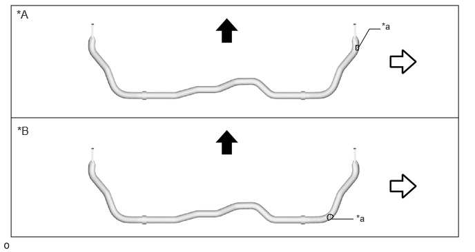
Make sure that the identification mark is positioned to the front stabilizer bar as shown in the illustration.
 0.167,0.083 6.917,3.583 6.75,3.5 0.167,1.781 6.917,1.781 false 5,3.313 5.333,3.313 false 5.417,0.708 5.573,0.438 5.573,0.438 5.74,0.438 false 0.25,0.115 0.625,0.354 0.375,0.24 12 false *A 0.26,1.875 0.635,2.115 0.375,0.24 12 false *B 5.375,3.219 5.688,3.417 0.313,0.198 10 false *a 5.76,0.313 6.073,0.51 0.313,0.198 10 false *a
*A for TFTM Made *B for GTMC Made *a Identification Mark - -
Front of the Vehicle
Right side of the Vhicle
48829A
4.INSTALL FRONT NO. 1 STABILIZER BRACKET LH
|
|
|
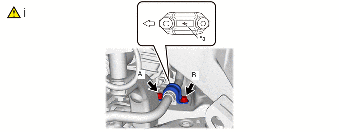
| *a | Arrow Mark | - | - |
|
|
Front of the Vehicle | - | - |
Install the front No. 1 stabilizer bracket LH to the front suspension crossmember sub-assembly with the 2 bolts.
- Torque:
- 103 N*m (1050 kgf*cm, 76 ft.*lbf)
48824A
5.INSTALL FRONT NO. 1 STABILIZER BRACKET RH
6.INSTALL WIRE HARNESS CLAMP BRACKET
48810
7.INSTALL FRONT STABILIZER LINK ASSEMBLY LH
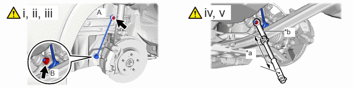
| *a | Torque Wrench Fulcrum Length | *b | Ball Joint Lock Nut Wrench |
Temporarily install the front stabilizer link assembly LH with the 2 nuts.
Fully tighten the nut A.
- Torque:
- 74 N*m (755 kgf*cm, 55 ft.*lbf)
- NOTICE:
-
Do not damage the boot of the ball joint.
If the ball joint turns together with the nut, use a 6 mm hexagon socket wrench to hold the stud bolt.
Using a ball joint lock nut wrench, fully tighten the nut B.
- Specified tightening torque:
74 N*m (755 kgf*cm, 55 ft.*lbf)
- NOTICE:
-
Do not damage the boot of the ball joint.
- HINT:
- ·
Calculate the torque wrench reading when changing the fulcrum length of the torque wrench.
·When using a ball joint lock nut wrench (fulcrum length of 149 mm (5.87 in.)) + torque wrench. (fulcrum length of 255 mm (10.04 in.)):
46.7 N*m (476 kgf*cm, 34 ft.*lbf)
If the ball joint turns together with the nut, use a 6 mm hexagon socket wrench to hold the stud bolt.
48820B
8.INSTALL FRONT STABILIZER LINK ASSEMBLY RH
9.INSTALL STEERING LINK ASSEMBLY