M20F-FXS, M20G-FXS ENGINE CONTROL SFI SYSTEM P210900 Throttle/Pedal Position Sensor "A" Minimum Stop Performance
DESCRIPTION
The idle speed is controlled by the Electronic Throttle Control System (ETCS). The ETCS is comprised of a throttle actuator, which operates the throttle valve, and a throttle position sensor, which detects the opening amount of the throttle valve. The ECM controls the throttle actuator to adjust the throttle valve opening amount so that the idle speed is maintained at the target idle speed.
| DTC No. | Detection Item | DTC Detection Condition | Trouble Area | MIL | Note |
|---|---|---|---|---|---|
| P210900 | Throttle/Pedal Position Sensor "A" Minimum Stop Performance | The ISC learned value is approximately 3 times larger than normal even though the actual intake air amount during idle is within the normal range (up to 1.5 times the normal amount) (1 trip detection logic). | Throttle body with motor assembly | Does not come on | SAE Code: P2109 |
- HINT:
- ·
The ISC learned value is the calculated intake air amount corresponding to the throttle opening amount necessary to maintain the idling speed.
·This malfunction is only detected once per trip. After it has been detected once, the system will not monitor for the malfunction for the rest of the trip.
·The system uses the throttle body with motor assembly and mass air flow meter to detect this malfunction.
MONITOR DESCRIPTION
If there are deposits in the throttle valve, a decrease in the ISC flow rate may cause engine stall or unstable idling. Therefore, the necessary ISC flow rate for idling is maintained using the ISC learned value and feedback. The ECM stores this DTC if the ISC learned value approaches its limit. The ECM begins monitoring for the DTC detection conditions when the following preconditions are met:
The mass air flow meter is normal.
Atmospheric pressure is 85 kPa(abs) [12.3 psi(abs)] or higher.
The vehicle has been driven at a speed of 30 km/h (19 mph) or more at least once.
The engine coolant temperature is 45°C (113°F) or less at engine start, the engine is warmed up and conditions for ISC learning are met, or the ignition switch has been turned on (IG) (include engine running) for 1 hour or more, the engine is warmed up and conditions for ISC learning are met.
CAUTION / NOTICE / HINT
- NOTICE:
- ·
Vehicle Control History may be stored in the hybrid vehicle control ECU assembly if the engine is malfunctioning. Certain vehicle condition information is recorded when Vehicle Control History is stored. Reading the vehicle conditions recorded in both the Freeze Frame Data and Vehicle Control History can be useful for troubleshooting.
(Select Powertrain in Health Check and then check the time stamp data.)
·If any "Engine Malfunction" Vehicle Control History item has been stored in the hybrid vehicle control ECU assembly, make sure to clear it. However, as all Vehicle Control History items are cleared simultaneously, if any Vehicle Control History items other than "Engine Malfunction" are stored, make sure to perform any troubleshooting for them before clearing Vehicle Control History.
- HINT:
- ·
Since a pending DTC is not stored for this DTC, it takes time to confirm whether the malfunction has been successfully repaired by checking for this DTC. When confirming whether the malfunction has been successfully repaired, compare "ISC Learning Value" recorded in the Freeze Frame Data with "ISC Learning Value" in the Data List after repairs have been made to save time.
·Read Freeze Frame Data using the GTS. The ECM records vehicle and driving condition information as Freeze Frame Data the moment a DTC is stored. When troubleshooting, Freeze Frame Data can help determine if the vehicle was moving or stationary, if the engine was warmed up or not, if the air fuel ratio was lean or rich, and other data from the time the malfunction occurred.
PROCEDURE
Read the DTCs.
- Powertrain > Engine > Trouble Codes
- 50001 372
- Result:
Result Proceed to DTC P210900 is output A DTC P210900 and other DTCs are output B
- HINT:
-
If any DTCs other than P210900 are output, troubleshoot those DTCs first.
A
B
Using the GTS, check "ISC Learning Value" in the Freeze Frame Data.
- Powertrain > Engine > DTC(P210900) > Freeze Frame Data
-
Tester Display ISC Learning Value - 50040 372 424 P210900
- HINT:
-
Be sure to confirm that the Freeze Frame Data item "ISC Learning Value" is the same as that used when confirming whether the malfunction has been successfully repaired.
- Result:
Proceed to NEXT
NEXT
Check for foreign matter between the throttle valve and the housing.
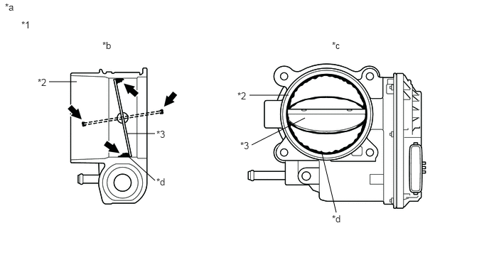
| *1 | Throttle Body with Motor Assembly | *2 | Bore |
| *3 | Throttle Valve | - | - |
| *a | Reference | *b | Throttle Body with Motor Assembly Cross-section Diagram |
| *c | When valve fully opened | *d | Deposits |
- HINT:
-
The illustration is for reference only, actual parts may differ.
- Result:
Result Proceed to Foreign matter between the throttle valve and housing A No foreign matter between the throttle valve and housing B
- HINT:
-
Perform "Inspection After Repair" after replacing the throttle body with motor assembly.
A
B
Clean off any deposits inside of the throttle body with motor assembly.
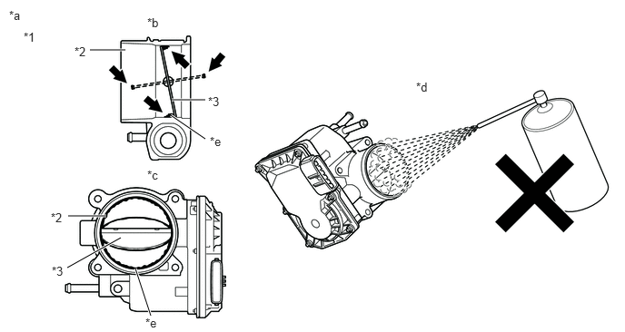
| *1 | Throttle Body with Motor Assembly | *2 | Bore |
| *3 | Throttle Valve | - | - |
| *a | Reference | *b | Throttle Body with Motor Assembly Cross-section Diagram |
| *c | When valve fully opened | *d | Do not directly apply cleaner |
| *e | Deposits | - | - |
Push open the throttle valve and wipe off any deposits from the valve and bore using a cloth soaked in non-residue solvent.
- NOTICE:
- ·
Make sure that the cloth or your fingers do not get caught in the valve.
·Make sure that foreign matter does not enter the throttle valve.
·Do not directly apply non-residue solvent to the throttle body with motor assembly or wash the throttle body with motor assembly. Cleaning solvent may leak into the motor from the shaft and cause problems such as rust or valve movement problems.
·If there is coating material on the edge of the throttle valve, be careful not to remove it.
·Push the throttle valve open gently with your finger and check that the throttle valve moves smoothly.
- HINT:
- ·
If the throttle valve does not open smoothly, replace the throttle body with motor assembly.
·The illustration is for reference only, actual parts may differ.
- Result:
Proceed to NEXT
NEXT
Perform "Inspection After Repair" after cleaning the throttle body with motor assembly.
Enter the following menus.
- Powertrain > Engine > Data List
-
Tester Display ISC Learning Value - 50003 372 424
According to the display on the GTS, read the Data List.
- OK:
The value of ISC Learning Value is half or less of ISC Learning Value recorded in the Freeze Frame Data.
- HINT:
-
Perform "Inspection After Repair" after replacing the throttle body with motor assembly.
- Result:
Proceed to OK NG
OK
NG