DRIVE SHAFT / PROPELLER SHAFT FRONT DRIVE SHAFT ASSEMBLY(for HEV Model) REMOVAL
CAUTION / NOTICE / HINT
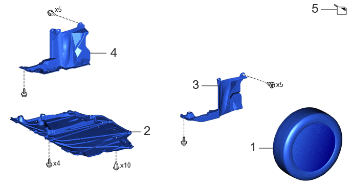
| Procedure | Part Name Code | 
|

|

|
|
|---|---|---|---|---|---|
| 1 | FRONT WHEELS | - | - | - | - |
| 2 | NO. 1 ENGINE UNDER COVER ASSEMBLY | 51410 | - | - | - |
| 3 | REAR ENGINE UNDER COVER LH | 51444A | - | - | - |
| 4 | REAR ENGINE UNDER COVER RH | 51443C | - | - | - |
| 5 | DRAIN HYBRID TRANSAXLE FLUID | - | - | ( 202307,999999,_52,_112266,_0604511,RM100000002BUWB_02_0065,) 202307,999999,_52,_112266,_0604511,RM100000002BUWB_02_0065,)
|
- |
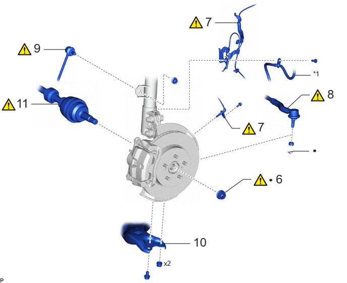
| Procedure | Part Name Code |
|
|
|
|
|---|---|---|---|---|---|
| 6 | FRONT AXLE SHAFT NUT | 43502H | (202307,999999,_52,_112266,_0604511,RM100000002BUWB_02_0068,)
|
- | - |
| 7 | FRONT SPEED SENSOR | 89543 | (202307,999999,_52,_112266,_0604511,RM100000002BUWB_02_0038,)
|
- | - |
| 8 | TIE ROD END SUB-ASSEMBLY | 45047 | (202307,999999,_52,_112266,_0604511,RM100000002BUWB_02_0039,)
|
- | - |
| 9 | FRONT STABILIZER LINK ASSEMBLY | 48810 | (202307,999999,_52,_112266,_0604511,RM100000002BUWB_02_0037,)
|
- | - |
| 10 | FRONT LOWER NO. 1 SUSPENSION ARM SUB-ASSEMBLY | 48069 | - | - | - |
| 11 | SEPARATE FRONT DRIVE SHAFT ASSEMBLY | 43420 | (202307,999999,_52,_112266,_0604511,RM100000002BUWB_02_0041,)
|
- | - |
| *1 | FRONT FLEXIBLE HOSE | - | - |
| ● | Non-reusable part | - | - |
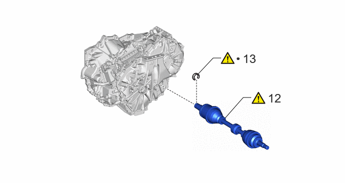
| Procedure | Part Name Code |
|
|
|
|
|---|---|---|---|---|---|
| 12 | REMOVE FRONT DRIVE SHAFT ASSEMBLY | 43420 | (202307,999999,_52,_112266,_0604511,RM100000002BUWB_02_0010,)
|
- | - |
| 13 | FRONT DRIVE SHAFT HOLE SNAP RING | 43420G | (202307,999999,_52,_112266,_0604511,RM100000002BUWB_02_0072,)
|
- | - |
| ● | Non-reusable part | - | - |
CAUTION / NOTICE / HINT
The necessary procedures (adjustment, calibration, initialization, or registration) that must be performed after parts are removed and installed, or replaced during the front drive shaft assembly removal/installation are shown below.
| Replacement Part or Procedure | Necessary Procedures | Effect/Inoperative Function When Necessary Procedures are not Performed | Link |
|---|---|---|---|
| Front wheel alignment adjustment | Calibration | ·
DTCs are stored ·
ABS warning light illuminates ·
Slip indicator light illuminates ·
VSC disabled or malfunctions |
(202307,999999,_54,_112606,_0608077,RM100000002C79U,)
|
| Suspension, tires, etc. | Parking assist ECU initialization | Panoramic view monitor system | (202201,999999,_56,_111969,_0587004,RM1000000029RN8,)
|
- HINT:
- ·
Use the same procedure for the RH side and LH side.
·The following procedure is for the LH side.
PROCEDURE

 1.REMOVE FRONT WHEELS
51410
2.REMOVE NO. 1 ENGINE UNDER COVER ASSEMBLY
51444A
3.REMOVE REAR ENGINE UNDER COVER LH
51443C
4.REMOVE REAR ENGINE UNDER COVER RH
5.DRAIN HYBRID TRANSAXLE FLUID
43502H
6.REMOVE FRONT AXLE SHAFT NUT
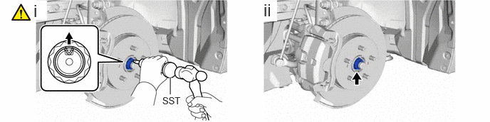
Using SST and a hammer, release the staked part of the front axle shaft nut.
- SST
- 09930-00010
- NOTICE:
-
Loosen the staked part of the front axle shaft nut completely, otherwise the threads of the drive shaft may be damaged.
While applying the brakes, using a 30 mm deep socket wrench, remove the front axle shaft nut.
89543
7.SEPARATE FRONT SPEED SENSOR
45047
8.SEPARATE TIE ROD END SUB-ASSEMBLY
48810
9.SEPARATE FRONT STABILIZER LINK ASSEMBLY
48069
10.SEPARATE FRONT LOWER NO. 1 SUSPENSION ARM SUB-ASSEMBLY
43420
11.SEPARATE FRONT DRIVE SHAFT ASSEMBLY
43420
12.REMOVE FRONT DRIVE SHAFT ASSEMBLY
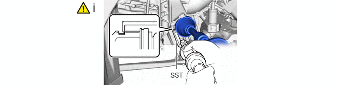
Using SST, remove the front drive shaft assembly.
- SST
- 09520-01011
09520-20010 (09521-02010, 09521-02040, 09521-02060)
- NOTICE:
- ·
Do not damage the front drive shaft oil seal.
·Do not damage the front axle inboard joint boot.
·Do not drop the front drive shaft assembly.
43420G
13.REMOVE FRONT DRIVE SHAFT HOLE SNAP RING
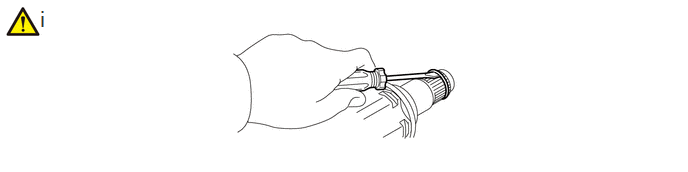
Using a screwdriver, remove the front drive shaft hole snap ring.