BRAKE SYSTEM (OTHER) BRAKE MASTER CYLINDER(for HEV Model) INSTALLATION
CAUTION / NOTICE / HINT
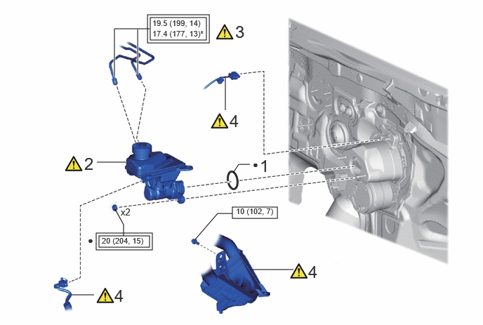
| Procedure | Part Name Code | 
|

|

|
|
|---|---|---|---|---|---|
| 1 | BRAKE MASTER CYLINDER O-RING | - | - | - | - |
| 2 | BRAKE MASTER CYLINDER SUB-ASSEMBLY | 47201 | ( 202307,999999,_54,_113942,_0604483,RM100000002BUHX_01_0001,) 202307,999999,_54,_113942,_0604483,RM100000002BUHX_01_0001,)
|
- | - |
| 3 | CONNECT BRAKE LINE | - | (202307,999999,_54,_113942,_0604483,RM100000002BUHX_01_0096,)
|
- | - |
| 4 | ENGINE ROOM MAIN WIRE | 82111 | (202307,999999,_54,_113942,_0604483,RM100000002BUHX_01_0100,)
|
- | - |

|
Tightening torque for "Major areas involving basic vehicle performance such as moving/turning/stopping" : N*m (kgf*cm, ft.*lbf) | 
|
N*m (kgf*cm, ft.*lbf): Specified torque |
| * | For use with a union nut wrench | ● | Non-reusable part |
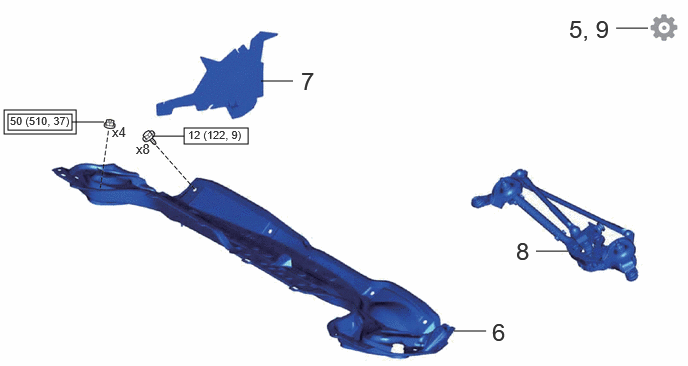
| Procedure | Part Name Code |
|
|
|
|
|---|---|---|---|---|---|
| 5 | BLEED BRAKE LINE | - | - | - | (202307,999999,_54,_113942,_0604483,RM100000002BUHX_01_0093,)
|
| 6 | OUTER COWL TOP PANEL SUB-ASSEMBLY | 55701J | - | - | - |
| 7 | NO. 1 HEATER AIR DUCT SPLASH SHIELD SEAL | 55737B | - | - | - |
| 8 | WINDSHIELD WIPER MOTOR AND LINK ASSEMBLY | - | - | - | - |
| 9 | INITIALIZATION AFTER RECONNECTING AUXILIARY BATTERY TERMINAL | - | - | - | (202307,999999,_54,_113942,_0604483,RM100000002BUHX_01_0099,)
|
|
|
Tightening torque for "Major areas involving basic vehicle performance such as moving/turning/stopping" : N*m (kgf*cm, ft.*lbf) |
|
N*m (kgf*cm, ft.*lbf): Specified torque |
PROCEDURE

 1.INSTALL BRAKE MASTER CYLINDER O-RING
47201
2.INSTALL BRAKE MASTER CYLINDER SUB-ASSEMBLY
|
|
|
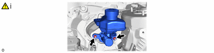
Install the brake master cylinder sub-assembly to the brake booster assembly with 2 new nuts.
- Torque:
- 20 N*m (204 kgf*cm, 15 ft.*lbf)
- NOTICE:
- ·
The brake master cylinder sub-assembly requires careful handling. Do not drop or subject the brake master cylinder sub-assembly to any impact. Do not reuse a brake master cylinder sub-assembly that has been dropped.
·Do not hold the brake master cylinder sub-assembly by the master cylinder piston. Hold the brake master cylinder sub-assembly by its body or its reservoir when carrying it.
·Do not pull out the master cylinder piston.
·Do not strike or pinch the master cylinder piston, or cause any damage to the master cylinder piston by any other means.
·When installing the brake master cylinder sub-assembly to the brake booster assembly, or when removing the brake master cylinder sub-assembly from the brake booster assembly, make sure that the brake master cylinder sub-assembly is kept horizontal or with its tip facing downward (the master cylinder piston is facing upward) to prevent the master cylinder piston from falling out.
·Do not allow any foreign matter to contaminate the master cylinder piston. If any foreign matter gets on the master cylinder piston, remove it by using a piece of new and dry cloth. Do not use water or detergent. Then apply an even layer of lithium soap base glycol grease around the circumference (sliding part) of the master cylinder piston.
·Do not use any other types of grease.
·Do not kink or damage the brake lines.
·Do not allow the brake lines to twist or interfere with other parts or the vehicle body during tightening.
·Do not allow any foreign matter such as dirt or dust to enter the brake lines from the connecting parts.
3.CONNECT BRAKE LINE
|
|
|
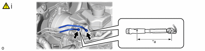
| *a | Torque Wrench Fulcrum Length | - | - |
Using a union nut wrench, connect the 2 brake lines to the brake master cylinder sub-assembly.
- Torque:
- Specified tightening torque : 19.5 N*m (199 kgf*cm, 14 ft.*lbf)
- HINT:
- ·
Calculate the torque wrench reading when changing the fulcrum length of the torque wrench.
·When using a union nut wrench (fulcrum length of 20 mm (0.787 in.)) + torque wrench (fulcrum length of 162 mm (6.38 in.)):
17.4 N*m (177 kgf*cm, 13 ft.*lbf)
82111
4.INSTALL ENGINE ROOM MAIN WIRE
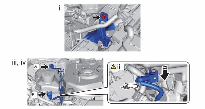

|
Push in this direction | 
|
Connect the connector in this direction |
Install the engine room main wire to the vehicle body with the bolt.
- Torque:
- 10 N*m (102 kgf*cm, 7 ft.*lbf)
Connect the connector (B) to the brake master cylinder reservoir assembly as shown in the illustration.
Engage the clamp to the brake master cylinder reservoir assembly.
Connect the connector (A) to the brake booster assembly.
5.BLEED BRAKE LINE
55701J
6.INSTALL OUTER COWL TOP PANEL SUB-ASSEMBLY
55737B
7.INSTALL NO. 1 HEATER AIR DUCT SPLASH SHIELD SEAL
8.INSTALL WINDSHIELD WIPER MOTOR AND LINK ASSEMBLY
9. INITIALIZATION AFTER RECONNECTING AUXILIARY BATTERY TERMINAL
- HINT:
-
When disconnecting and reconnecting the auxiliary battery, there is an automatic learning function that completes learning when the respective system is used.