BRAKE CONTROL / DYNAMIC CONTROL SYSTEMS BRAKE CONTROL POWER SUPPLY INSTALLATION
CAUTION / NOTICE / HINT
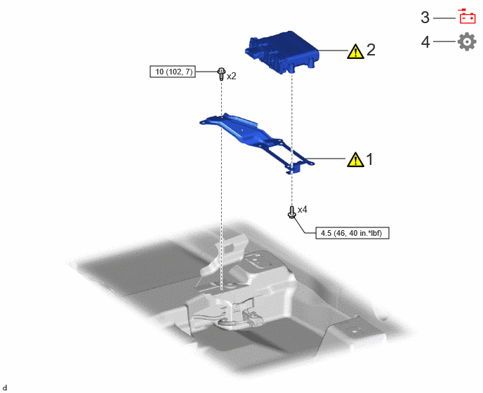
| Procedure | Part Name Code | 
|

|

|
|
|---|---|---|---|---|---|
| 1 | NO. 1 BRAKE CONTROL POWER SUPPLY BRACKET | 89686A | ( 202307,999999,_54,_112606,_0604465,RM100000002BUF3_01_0006,) 202307,999999,_54,_112606,_0604465,RM100000002BUF3_01_0006,)
|
- | - |
| 2 | BRAKE CONTROL POWER SUPPLY ASSEMBLY | 89680 | (202307,999999,_54,_112606,_0604465,RM100000002BUF3_01_0005,)
|
- | - |
| 3 | CONNECT CABLE TO NEGATIVE AUXILIARY BATTERY TERMINAL | - | - | - | - |
| 4 | INITIALIZATION AFTER RECONNECTING AUXILIARY BATTERY TERMINAL | - | - | - | (202307,999999,_54,_112606,_0604465,RM100000002BUF3_01_0001,)
|

|
N*m (kgf*cm, ft.*lbf): Specified torque | - | - |
PROCEDURE

 89686A
1.INSTALL NO. 1 BRAKE CONTROL POWER SUPPLY BRACKET
89686A
1.INSTALL NO. 1 BRAKE CONTROL POWER SUPPLY BRACKET
|
|
|
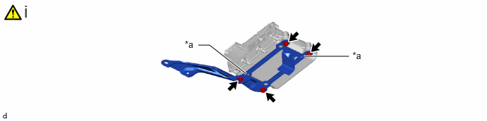
| *a | Protrusion | - | - |
Install the No. 1 brake control power supply bracket with 4 bolts.
- Torque:
- 4.5 N*m (46 kgf*cm, 40 in.*lbf)
- NOTICE:
-
Align the hole on the No. 1 brake control power supply bracket with the protrusion of the brake control power supply assembly.
89680
2.INSTALL BRAKE CONTROL POWER SUPPLY ASSEMBLY
|
|
|
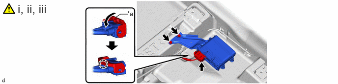
| *a | Lock lever | - | - |
Connect the brake control power supply assembly connector and push down the lock lever to engage the claw as shown in the illustration.
- NOTICE:
- ·
When connecting the brake control power supply assembly connector, make sure that the connecting parts of the brake control power supply assembly connector are free of dirt, water or other foreign matter.
·Be sure to securely connect the brake control power supply assembly connector.
Install the brake control power supply assembly with the 2 bolts.
- Torque:
- 10 N*m (102 kgf*cm, 7 ft.*lbf)
Install the floor carpet.
3.CONNECT CABLE TO NEGATIVE AUXILIARY BATTERY TERMINAL
4. INITIALIZATION AFTER RECONNECTING AUXILIARY BATTERY TERMINAL
- HINT:
-
When disconnecting and reconnecting the auxiliary battery, there is an automatic learning function that completes learning when the respective system is used.