M20F-FXS, M20G-FXS INTAKE / EXHAUST INTAKE MANIFOLD REMOVAL
CAUTION / NOTICE / HINT
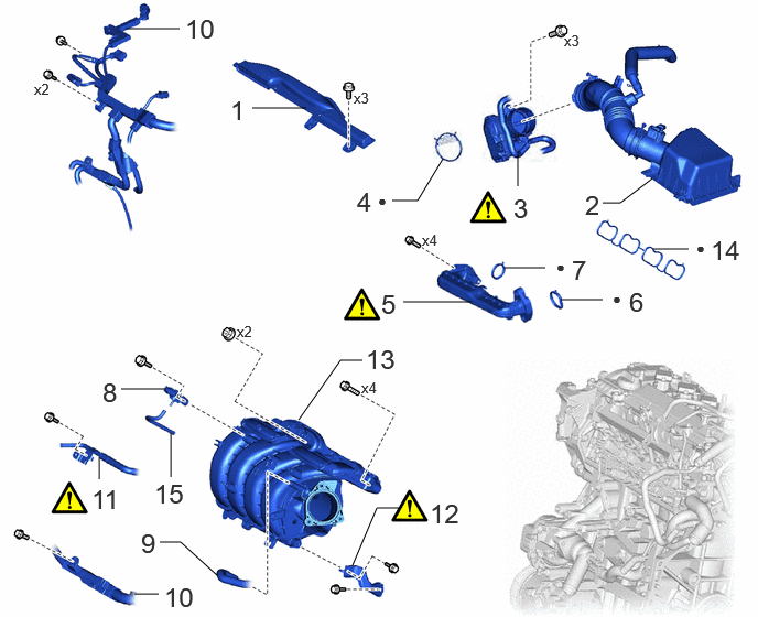
| Procedure | Part Name Code | 
|

|

|
|
|---|---|---|---|---|---|
| 1 | INLET NO. 1 AIR CLEANER | 17751 | - | - | - |
| 2 | AIR CLEANER CAP WITH AIR CLEANER HOSE | - | - | - | - |
| 3 | THROTTLE BODY WITH MOTOR ASSEMBLY | 22030 | ( 202307,999999,_51,_144997,_0604322,RM100000002BTVQ_01_0134,) 202307,999999,_51,_144997,_0604322,RM100000002BTVQ_01_0134,)
|
- | - |
| 4 | THROTTLE BODY GASKET | 22271 | - | - | - |
| 5 | NO. 1 EGR PIPE SUB-ASSEMBLY | 25601 | (202307,999999,_51,_144997,_0604322,RM100000002BTVQ_01_0171,)
|
- | - |
| 6 | EGR VALVE ADAPTER GASKET | 25629 | - | - | - |
| 7 | EGR INLET GASKET | 25628 | - | - | - |
| 8 | E.F.I. VACUUM SENSOR ASSEMBLY (MANIFOLD ABSOLUTE PRESSURE SENSOR) | 89421 | - | - | - |
| 9 | NO. 1 FUEL VAPOR FEED HOSE | 23826 | - | - | - |
| 10 | ENGINE WIRE | 82121 | - | - | - |
| 11 | NO. 2 WATER BY-PASS PIPE | 16278 | (202307,999999,_51,_144997,_0604322,RM100000002BTVQ_01_0183,)
|
- | - |
| 12 | INTAKE MANIFOLD STAY | 17138B | (202307,999999,_51,_144997,_0604322,RM100000002BTVQ_01_0178,)
|
- | - |
| 13 | INTAKE MANIFOLD | 17111 | - | - | - |
| 14 | NO. 1 INTAKE MANIFOLD TO HEAD GASKET | 17177 | - | - | - |
| 15 | VACUUM HOSE | - | - | - | - |
| ● | Non-reusable part | - | - |
CAUTION / NOTICE / HINT
The necessary procedures (adjustment, calibration, initialization or registration) that must be performed after parts are removed and installed, or replaced during intake manifold removal/installation are shown below.
| Replaced Part or Performed Procedure | Necessary Procedure | Effect/Inoperative Function when Necessary Procedure not Performed | Link |
|---|---|---|---|
·
Replacement of throttle body with motor assembly ·
Cleaning the deposits from the throttle body with motor assembly ·
Gas leak from exhaust system is repaired |
Inspection After Repair | ·
Poor idle, etc. ·
Engine start function, etc. |
(202307,999999,_51,_144956,_0604911,RM100000002BWPD,)
|
- CAUTION:
- ·
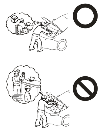
·Orange wire harnesses and connectors indicate high-voltage circuits. To prevent electric shock, always follow the procedure described in the repair manual.
·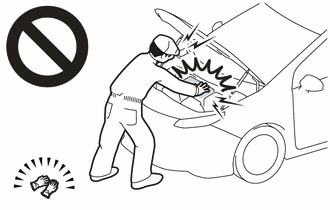
To prevent electric shock, wear insulated gloves when working on wire harnesses and components of the high voltage system.
- NOTICE:
- ·
After the power switch is turned off, the radio and display receiver assembly records various types of memory and settings. As a result, after turning the power switch off, make sure to wait at least 85 seconds before disconnecting the cable from the negative (-) auxiliary battery terminal. (for Audio and Visual System (for HV Model))
·After the power switch is turned off, the radio and display receiver assembly records various types of memory and settings. As a result, after turning the power switch off, make sure to wait at least 85 seconds before disconnecting the cable from the negative (-) auxiliary battery terminal. (for Navigation System (for HV Model))
·This procedure includes the removal of small-head bolts. Refer to Small-Head Bolts of Basic Repair Hint to identify the small-head bolts.
- NOTICE:
- ·
After the ignition switch is turned off, the radio and display receiver assembly records various types of memory and settings. As a result, after turning the ignition switch off, make sure to wait at least 2 minutes before disconnecting the cable from the negative (-) auxiliary battery terminal. (w/ Radio and Display Receiver assembly)
·This procedure includes the removal of small-head bolts. Refer to Small-Head Bolts of Basic Repair Hint to identify the small-head bolts.
PROCEDURE

 17751
1.REMOVE INLET NO. 1 AIR CLEANER
17751
1.REMOVE INLET NO. 1 AIR CLEANER
2.REMOVE AIR CLEANER CAP WITH AIR CLEANER HOSE
22030
3.SEPARATE THROTTLE BODY WITH MOTOR ASSEMBLY

Disconnect the throttle body with motor assembly connector.
Using an 8 mm socket wrench, remove the 3 bolts to separate the throttle body with motor assembly from the intake manifold.
22271
4.REMOVE THROTTLE BODY GASKET
25601
5.REMOVE NO. 1 EGR PIPE SUB-ASSEMBLY
25629
6.REMOVE EGR VALVE ADAPTER GASKET
25628
7.REMOVE EGR INLET GASKET
89421
8.REMOVE E.F.I. VACUUM SENSOR ASSEMBLY (MANIFOLD ABSOLUTE PRESSURE SENSOR)
23826
9.REMOVE NO. 1 FUEL VAPOR FEED HOSE

82121
10.DISCONNECT ENGINE WIRE
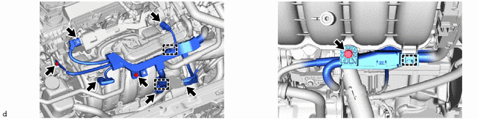
16278
11.DISCONNECT NO. 2 WATER BY-PASS PIPE
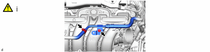
Using an 8 mm socket wrench, remove the bolt and separate the No. 2 water by-pass pipe from the intake manifold.
17138B
12.REMOVE INTAKE MANIFOLD STAY

Using an 8 mm socket wrench, remove the bolt (A).
Remove the bolt (B).
Disengage the guide and remove the intake manifold stay.
17111
13.REMOVE INTAKE MANIFOLD

17177
14.REMOVE NO. 1 INTAKE MANIFOLD TO HEAD GASKET

15.REMOVE VACUUM HOSE